background image


37 


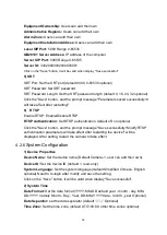
Time, Font and Color:

 Default white, black, yellow, red and blue optional)   

Title Font Color:

 Default white, black, yellow, red, and blue optional) 

Move Character: 

Set the location where the time and title to display. Click “ up, 

down, left, right” button to move the characters’ location. 

Title

: Set title on device property (default CAMERA1) 

Time

: Set time on system time (default 1970/01/01 05:36:00) 

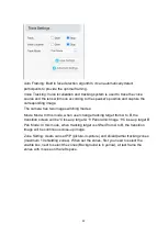
Click “Save” button, “parameters are successfully saves” window pop-up, which 
means the setting take effect. 

6

Character Size 

Automatically Adjust According to the Resolution: 

Yes/No 

Main Stream Character Size:

 Set the character size of the display, the device will 

automatically restart after changed (default 48, 28-200 optional) 

Secondary Stream Character Size: 

Set the character size of the display, the device 

will automatically restart after changed (default 48, 28-200 optional) 

Click “Save” button, “parameters are successfully saves” window pop-up, which 
means the setting take effect. 

7

Video Output 

Output Format:

 Set the video output format   

Click “Save” button, “parameters are successfully saves” window pop-up, which 
means the setting take effect. 

4.2.5 

Network Configuration 

1) Network Port 

Data Port:

 set the data port, the device will restart automatically after changed 

(default 3000,0-65535 optional). 

Web Port: 

Set Web port, the device will restart automatically after changed (default 

is 80, 0-65535 is optional). 

Onvif Port: 

Set Onvif port, the device will restart automatically after changed (default 

2000, 0-65535 optional). 

Soap Port:

 Set Soap port (default 1936, 0-65535 optional). 

RTMP Port: 

Set RTMP port (default 1935, 0-65535 optional). 

RTSP Port: 

Set RTSP port, the device will restart automatically after changed 

(default 554,0-65535 optional). 

Visca Port: 

Set Visca port, the device will restart automatically after changed (default 

3001,0-65535 optional). 

Summary of Contents for DVDO-C7-1

Page 1: ...DVDO C7 1 4K PTZ Camera Version V1 0 0 User Manual...

Page 2: ...mera operation Graphic Symbols Description of graphic symbols used in this manual Symbols Description This symbol indicates that the words are clarification or supplement to this article This symbol i...

Page 3: ...mage the surface Electrical Safety Installation and product use must strictly comply with local electrical safety standards Transportation Avoid any stress vibration or moisture during transportation...

Page 4: ...1 4 2 Steps of Ceiling Mount 4 Product Overview 5 2 1 Product Overview 5 2 1 1 Product Dimensions 5 2 1 2 Accessory 5 2 2 Product Feature 6 2 3 Technical Specification 7 2 4 Interface Introduction 12...

Page 5: ...onfiguration 33 4 2 4 Video Configuration 33 4 2 5 Network Configuration 37 4 2 6 System Configuration 39 4 2 7 Logout 41 4 2 8 Tracking Function Configuration 41 Serial Port Communication Control 43...

Page 6: ...3 Panoramic Lens 4 Remote Control Receiving Light 9 HDMI Output 10 LAN Port 5 Screw Hole for Tripod 11 RS232 Input 6 Position Hole for Tripod 12 Power Input Socket When using the camera please put th...

Page 7: ...network HDMI and USB3 0 1 3 1 Network Output a Network connection Shown as diagram 1 1 10 b Log in You can reach the Web Interface by typing in the camera s IP address default 192 168 5 163 into a we...

Page 8: ...1 4 Bracket Bracket can only be wall mounted or upside down mounted on template and concrete wall but can not be installed on plasterboard 1 4 1 Steps for Wall Mounting Figure1 2 Steps for Wall Mounti...

Page 9: ...4 1 4 2 Steps for Ceiling Mounting Figure1 3 Steps for Ceiling Mounting...

Page 10: ...1 1 Product Dimensions Figure1 4 Product Dimension 2 1 2 Accessory When you unpack your package check that all the supplied accessories are included Supplied Accessory Supplied Power adapter USB3 0 C...

Page 11: ...achieved with low noise CMOS Advanced 2D 3D noise reduction technology further reduces the noise while ensuring high image clarity Multiple Video Output Methods Support HDMI USB3 0 wired LAN interface...

Page 12: ...gent Voice Tracking Built in 6 omnidirectional mics arrays intelligent voice localization algorithm it can track the speaker in the real time Multiple Application Online education Lecture Capture Webc...

Page 13: ...e up Lens 12X Viewing Angle H 7 6 N 80 5 W Iris Value F1 8 F3 6 Digital Zoom 15X Minimum Illumination 0 5Lux F1 8 AGC ON DNR 2D 3D White Balance Auto Manual One Button White Balance Specified Color Te...

Page 14: ...io Output HDMI LAN USB3 0 Audio Compression Formats AAC MP3 G 711A Network Port 10M 100M adaptive Ethernet port support POE power supply support audio and video output Network Protocols RTSP RTMP ONVI...

Page 15: ...110 110 Tilt Angle 30 30 Pan Speed 0 1 s 100 s Tilt Speed 0 1 s 70 s Preset Speed Pan 78 8 s Tilt 31 7 s Preset Quantity Maximum 255 10 via remote control Other Parameter Others Storage Temperature 10...

Page 16: ...on brackets AI Function AI Function Auto Framing Built in high speed processor and face detection algorithm it can automatically detect the participants to provide optimal framing Intelligent Voice Tr...

Page 17: ...terface Diagram The interfaces of this product include HDMI USB3 0 and audio input interface network interface RS232 input DC12V power supply interface power switch The back panel diagram is shown in...

Page 18: ...13 2 4 2 RS 232 1 RS 232 Diagram Connecting method to PC or controller Device WindowsDB 9 1 DTR 1 DCD 2 DSR 2 RXD 3 TXD 3 TXD 4 GND 4 DTR 5 RXD 5 GND 6 GND 6 DSR 7 IR OUT 7 RTS 8 NC 8 CTS 9 RI...

Page 19: ...TXD Transmit Data 4 GND System Ground 5 RXD Receive Data 6 GND System Ground 7 IR OUT IR Commander Signal IR 8 NC No Connection RS232 DB9 Terminal Port Definition NO Terminal Port Definition NO Termin...

Page 20: ...onnection Method Device 1 Device 2 1 DTR 1 DTR 2 DSR 2 DSR 3 TXD 3 TXD 4 GND 4 GND 5 RXD 5 RXD 6 GND 6 GND 7 IR OUT 7 OPEN 8 NC 8 OPEN Figure1 6 VISCA Networking Diagram This camera has RS232 Input Ou...

Page 21: ...er Button combination 2 SDI HDMI Output Connect the monitor with the corresponding video output interface 3 USB3 0 Output Connect this product with computer USB3 0 interface open the Device Manager to...

Page 22: ...After the code is successfully matched you need to select the camera address to control it 2 Clear Code Data Press the Settings Button Button from light off to flashing the receiving end is powered o...

Page 23: ...y mode Long press 3S again the camera will self test again and back to HOME position Note If power on mode is turned on and Preset 0 is set and there is no operation within 12s it will automatically p...

Page 24: ...ra Address No 1 F2 Camera Address No 2 F3 Camera Address No 3 F4 Camera Address No 4 12 Button Combination Functions Clear all presets 0 Switch Video Format into 4KP30 6 Restore Factory Default 1 Swit...

Page 25: ...e second is required 2 When a Button combination is required do it in sequence For example F1 means press first and then press and last press F1 1 Camera Selection Select the camera address to control...

Page 26: ...rs should press the SET PRESET Button first and then press the number Button 0 9 to set a relative preset Note 10 preset positions in total are available by remote controller 2 Preset Running Press a...

Page 27: ...Enter into submenu of system setting Camera Parameter Enter into submenu of camera parameter P T Z Enter into submenu of PTZ parameter Version Enter into submenu of version Revise Press to revise para...

Page 28: ...D Auto Visca ADDR VISCA 1 7 Pelco P 1 255 Pelco D 1 255 Visca Address Fix On Off USB Dual Stream On Off Auto Flip On Off Track Setting Auto Framing ON OFF Voice Location ON OFF Track Mode Pan Movies...

Page 29: ...ter into noise reduction Style Default standard clear bright soft 1 Exposure Move the pointer to the EXPOSURE in the Main Menu click the HOME and enter the EXPOSURE SET as follow Mode Auto Manual Shut...

Page 30: ...8 0 F6 8 F5 6 F4 8 F4 0 F3 4 F2 8 F2 4 F2 0 F1 8 only available in Manual and Iris priority mode Brightness 0 20 only available in Brightness priority mode 2 Color Move the pointer to the COLOR in the...

Page 31: ...the IMAGE as follow Brightness 0 100 Contrast 0 100 Sharpness 0 15 B W Mode Color black white DZoom On Off Gama Curve Default 0 45 0 50 0 55 0 63 Minimum Illumination On Off 4 Focus Move the pointer...

Page 32: ...k the HOME and enter the NOISE REDUCTION as follow 2D Noise Reduction Off 1 8 3D Noise Reduction Off 1 8 3 3 5 P T Z Move the pointer to the P T Z in the Main Menu click the HOME and enter the P T Z a...

Page 33: ...8 Image Freezing On Off Accelerating Curve Fast slow Preset Speed 1 10 3 3 6 Video Format Move the pointer to the Video Format in the Menu click the HOME and enter the Video Format as follow P T Z Spe...

Page 34: ...ick the HOME and enter the VERSION as follow Restore default Yes No after restoring default the language color and video format won t be restored If the address of former remoter is not 1 but another...

Page 35: ...open the window of Local Area Connection Properties on computer select the Internet protocol version 4 TCP IPv4 as shown by picture on the left Double click or click the property Internet protocol ve...

Page 36: ...rk connection as steps above mentioned after the finish of camera self check If IP is default open DOS command window and input 192 168 5 163 then press Enter Button It will show message as below whic...

Page 37: ...interface display English click English 2 Download Plug in When first using IE browser to access the web conferencing camera the login page will appear Playback plug in is not installed please downloa...

Page 38: ...video output setting etc Network Configuration Including basic parameters Ethernet DNS wireless network setting GB28181 etc System Configuration Including equipment property system time user manageme...

Page 39: ...e When streaming via rtsp or rtmp user can modify stream name Main Stream live av0 sub stream live av1 Click the Save button to display the Parameter saved successfully message then settings take effe...

Page 40: ...Set the gain limits valid in auto focus iris priority and brightness priority Gain Set gain only valid in manual exposure mode and shutter priority default 0 0 20 optional Dynamic Range Set the dynami...

Page 41: ...ess Set the sharpness value default 6 0 15 optional Gamma Gamma value setting default 0 45 0 50 0 55 0 63 optional Dynamic Contrast Set dynamic contrast default off 1 8 optional BW Mode Set black and...

Page 42: ...estart after changed default 48 28 200 optional Click Save button parameters are successfully saves window pop up which means the setting take effect 7 Video Output Output Format Set the video output...

Page 43: ...his IP address is the same with the one used to login Web page Subnet Mask Set the subnet mask default 255 255 255 0 Default Gateway Set the default gateway default 0 0 0 0 Physical Address Set the ph...

Page 44: ...SP Authentication Set RTSP authentication default off on optional Click the Save button and the prompt message Save successfully Modify RTSP authentication parameters will take effect after restarting...

Page 45: ...Administrator default admin select a common user1 default user1 to select a common user 2 default user2 user can modify their own Password Set a password Select User Administrator default admin select...

Page 46: ...the device will restart automatically and restore factory setting 6 Reboot Click Reboot button and choose yes or no on the pop up window then the device will restart automatically 4 2 7 Logout Click L...

Page 47: ...Movie Mode In this mode when user change tracking target from A to B the transition screen will be Close up target A Panoramic Image Close up target B Pan Mode In this mode when tracking target is sh...

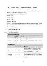
Page 48: ...hen pulled back after that self test is completed 5 1 VISCA Protocol List 5 1 1 VISCA Protocol List Ack Completion Message Command packet Remark ACK z0 41 FF Returned when the command is accepted Comp...

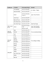
Page 49: ...executed due to current conditions For example when commands controlling the focus manually are received during auto focus 5 1 2 Camera Control Command Command Function Command Packet Remark AddressS...

Page 50: ...8x 01 04 47 0p 0q 0r 0s 0t 0u 0v 0w FF pqrs Zoom Position tuvw Focus Position CAM_AF Sensitivity High 8x 01 04 58 01 FF Focus sensitivity Setting Normal 8x 01 04 58 02 FF Low 8x 01 04 58 03 FF CAM_AF...

Page 51: ...etting Normal 8x 01 04 A9 01 FF High 8x 01 04 A9 02 FF CAM _RGain Reset 8x 01 04 03 00 FF Manual Control of R Gain Up 8x 01 04 03 02 FF Down 8x 01 04 03 03 FF Direct 8x 01 04 43 00 00 0p 0q FF pq R Ga...

Page 52: ...2 FF Down 8x 01 04 0B 03 FF Direct 8x 01 04 4B 00 00 0p 0q FF pq Iris Position CAM_Gain Limit Reset 8x 01 04 0C 00 FF Gain Limit Setting Up 8x 01 04 0C 02 FF Down 8x 01 04 0C 03 FF Gain Limit 8x 01 04...

Page 53: ...Level Positon CAM_NR 2D 8x 01 04 53 0p FF P 0 7 0 OFF 3D 8x 01 04 54 0p FF P 0 8 0 OFF CAM_Gamm a 8x 01 04 5B 0p FF p 0 4 0 Default 1 0 45 2 0 50 3 0 55 4 0 63 CAM_Low Light Mode ON 8x 01 04 2D 01 FF...

Page 54: ...8x 01 04 61 02 FF Image Flip Horizontal ON OFF Off 8x 01 04 61 03 FF CAM_Picture Flip On 8x 01 04 66 02 FF Image Flip Vertical ON OFF Off 8x 01 04 66 03 FF CAM_ColorS aturation Direct 8x 01 04 49 00...

Page 55: ...01 FF Flip V 8x 01 04 A4 02 FF Flip HV 8x 01 04 A4 03 FF CAM_VideoS ystem Set Camera video system 8x 01 06 35 00 0p FF P 0 E Video format 0 4KP30 1 4KP25 2 1080P30 3 1080P25 4 1080P29 97 Pan_tiltDrive...

Page 56: ...ion 8x 01 06 03 VV WW 0Y 0Y 0Y 0Y 0Z 0Z 0Z 0Z FF Home 8x 01 06 04 FF Reset 8x 01 06 05 FF Pan tilt LimitSet Set 8x 01 06 07 00 0W 0Y 0Y 0Y 0Y 0Z 0Z 0Z 0Z FF W 1 Up Right 0 DownLeft YYYY Pan Limit Posi...

Page 57: ...0q 0r 0s FF pqrs Focus Position CAM_AFSensi tivityInq 8x 09 04 58 FF y0 50 01 FF High y0 50 02 FF Normal y0 50 03 FF Low CAM_AFZone Inq 8x 09 04 AA FF y0 50 00 FF Front y0 50 01 FF Beting y0 50 02 FF...

Page 58: ...Inq 8x 09 04 39 FF y0 50 00 FF Full Auto y0 50 03 FF Manual y0 50 0A FF Shutter priority y0 50 0B FF Iris priority y0 50 0D FF Bright CAM_Shutter PosInq 8x 09 04 4A FF y0 50 00 00 0p 0q FF pq Shutter...

Page 59: ...z CAM_Apertur eInq 8x 09 04 42 FF y0 50 00 00 0p 0q FF pq Aperture Gain CAM_PictureE ffectModeInq 8x 09 04 63 FF y0 50 00 FF Off y0 50 04 FF B W CAM_Memory Inq 8x 09 04 3F FF y0 50 0p FF p Memory numb...

Page 60: ...00 FF Off y0 50 01 FF Flip H y0 50 02 FF Flip V y0 50 03 FF Flip HV CAM_Gamma Inq 8x 09 04 5B FF y0 50 0p FF p Gamma setting CAM_VersionI nq 8x 09 00 02 FF y0 50 ab cd mn pq rs tu vw FF ab cd vender I...

Page 61: ...0x10 Pan Speed Tilt Speed SUM Left 0xFF Address 0x00 0x04 Pan Speed Tilt Speed SUM Right 0xFF Address 0x00 0x02 Pan Speed Tilt Speed SUM Upleft 0xFF Address 0x00 0x0C Pan Speed Tilt Speed SUM Upright...

Page 62: ...an Position 0xFF Address 0x00 0x51 0x00 0x00 SUM Query Pan Position Response 0xFF Address 0x00 0x59 Value High Byte Value Low Byte SUM Query Tilt Position 0xFF Address 0x00 0x53 0x00 0x00 SUM Query Ti...

Page 63: ...58 5 3 Pelco P Protcol Command List...

Page 64: ...DownLeft 0xA0 Address 0x00 0x14 Pan Speed Tilt Speed 0xAF XOR DownRight 0xA0 Address 0x00 0x12 Pan Speed Tilt Speed 0xAF XOR Zoom In 0xA0 Address 0x00 0x20 0x00 0x00 0xAF XOR Zoom Out 0xA0 Address 0x0...

Page 65: ...ilt Position 0xA0 Address 0x00 0x53 0x00 0x00 0xAF XOR Query Tilt Position Response 0xA0 Address 0x00 0x5B Value High Byte Value Low Byte 0xAF XOR Query Zoom Position 0xA0 Address 0x00 0x55 0x00 0x00...

Page 66: ...er Do not operate close to powerful electromagnetic radiation such as TV or radio transmitters etc 6 3 Troubleshooting No image 1 Check whether the power cord is connected voltage is OK POWER lamp is...

Page 67: ...tal and level surface 2 Check the building and any supporting furniture for vibration Ceiling mounts are often affected by building vibration more than wall mounts 3 Any external vibration that is aff...

Page 68: ...y not be cloned copied or translated in any way without the explicit permission of the company Product specifications and information referred to in this document are for reference only and as such ar...

Reviews: