Instruction Manual ERA REGENERATOR
21
ENGLISH
instruction
manual
ERA REGENERATOR
previous cylce has not been completed correctly.
The salt alarm can be switched off by keeping pressed the
–
key and selecting the
OK
+
OK
+
sequence.
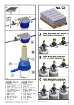
Salt presence in the brine tank (fig.1, D) shall always been
plentiful so as to ensure correct regeneration of softeners.
WARNING:
Please use refined food grade salt that also fits softeners. The
brine tank lid shall always be kept closed so as to avoid dust
or insects contamination; moreover, this prevents that small
objects that might accidentally fall in the tank damage the
equipment or the quality and healthiness of the treated water.
Please use a specific tool to add salt and avoid placing salt
bags on the edge of the brine tank.
The brine tank shall be cleaned every 6 months or, in any
case, each time the tank or the
float are visibly foul (fig. 1, U).
Cleaning shall be carried out by using a wet rug and lukewarm
water.
Do not use detergents or other chemical or abrasive pro-
ducts.
9) RINSE
The ERA regenerator can be configured so as to have a simple
rinse cycle for softeners.
This function might be useful when you want to rinse an ER
cylinder that has not been used for an extended period and
that has to be installed.
1. In order to carry out the rinse cycle, follow the instructions
illustrated in chapter 8 “REGENERATION” up to step 7.
2. Check that the display shows the right model and number
of cylinders to be rinsed (if it is not the right information,
see par. 6.2)
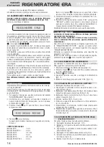
3. Keep pressed the
–
key for 5 seconds until you read the
following message:
4. Press
OK
to confirm.
Once you get to this step, a rinse cycle will start. The rinse
time duration is proposed herein:
RINSE TIME DURATION
Model ER5:
. . . . . . . . . . .
1 min
Model ER8-ER10:
. . . . . . .
2 min
Model ER12:
. . . . . . . . . .
2,5 min
Model ER14:
. . . . . . . . . .
3 min
Model ER16:
. . . . . . . . . .
3,5 min
Model ER18-ER20:
. . . . . .
4 min
If the
OK
button is not pressed, there will be no rinse cycle
and after some seconds the display will go back to the
main screen.
5. Once the rinse cycle is over, please check that there are no
alarm messages on the display.
6. Turn the knobs on the “ERV” valves to “REPLACE”, pull
apart the two gray blocks to unfasten the valves (fig. 4, B),
disconnect the softener by removing the ERV valve(s) from
the cylinder(s).
The softeneres are ready to be used again.
10) MAINTENANCE
The ERA regeneration equipment does not require any
specific maintenance procedure. It monitors salt level
in the brine tank and tells, via the ERA gearcase, when
maintenance interventions are needed
.
After 300 regeneration cycles, the display will show “EJECTOR
MAINTENANCE”;
after 600 regeneration cycles, the display will show “PISTON
MAINTENANCE”.
The two maintenance procedures are illustrated in paragraph
10.2 and 10.3 respectively.
Moroeover, verifying the number of completed regenerations
is possible by pressing the
+
key, as described in chapter
11.
10.1 REGENERATOR DISCONNECTION
Maintenance can be carried out after having disconnected the
ERA gearcase. Instructions are proposed herein.
1. Close the infeed water tap (fig. 1, G)
2. Keep the
–
key pressed for 5 seconds so as to read the
“RINSE” message
3. Press
OK
to confirm
4. Wait for a few seconds and then disconnect the electrical
connector (fig.1, E)
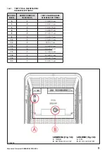
5. Unscrew the fixing screws located under “ERA” (fig. 2, D)
10.2 INSTRUCTIONS FOR EJECTOR CLEANING
1. Disconnect the equipment (see par. 10.1).
2. Turn upside down the gearcase so as to able to see the
internal components (fig. 5).
3. Disconnect the ERV valve pipes (fig. 5, M). Unscrew the
plastic nut used for the outlet part (fig. 5, N).
4. Disconnect the small motor faston connectors (fig. 5, K)
and, by using a wrench, unscrew the coupling (fig. 5, I).
5. Gently pull out the ejector (fig. 5, H).
6. Clean the ejector in running water and check that the ejec-
tor hole is not clogged.
7. Put the ejector back in its housing by pushing it down to
the mechanical stop.
8. Reassemble the equipment by following this same in-
structions backward; make sure you correctly install the
motor faston connectors (fig. 5, K).
10.3 INSTRUCTIONS ON HOW TO CLEAN THE BLOCK
VALVE PISTON
The procedure for cleaning the piston in the block valve is
herein proposed:
1. Disconnect the equipment (see par. 10.1).
2. Unscrew the two screws located at the bottom of the ge-
arcase (fig. 2, D).
3. Turn upside down the gearbox so as to be able to see all
the internal components (fig. 5).
4. Disconnect the 3 block valve pipes (fig. 5, P).
5. Pull out the connector with the electrodes located on top
of the block valve (fig. 5, A).
6. Unscrew the valve coupling (fig. 5, G).
7. Pull out the piston (fig.5, E) without damaging the spring
(fig. 5, F).
8. Clean the piston and the electrods under running water,
then replace the piston gaskets (fig.5, E).
9. Put back in their housing the piston, the spring and the
electrodes, then fasten the coupling to the valve body.
10. Reassemble the equipment by following this same in-
structions backward; make sure you correctly install the
electrode connector and the three block valve pipes, whi-
ch have to be pushed down to the mechanic stop (see
par. 3.3.2).
10.4 FILTER CARTRIDGE REPLACEMENT
Filter cartridge replacement is advisable in order to keep the
RESIN RINSE

