Manual RMO-H
M-RH00NN-300-EN
9
To maximize accuracy and measurement repeatability make sure that all clamps have a good
connection to the test object and avoid any connection between Sense and Current clamps.
In case that combined current and sense cables are provided with the RMO-H device, the user only
needs to connect the TTA clamps to the connection points. The resistance between these points will be
measured by the device.
3.2 Connecting RMO-H to Circuit Breaker
Before connecting the RMO-H to a circuit breaker make sure that:
the breaker is disconnected or separated from its circuit on both sides of the breaker in
accordance with the national safety regulations;
always comply with local safety regulations
when using the RMO-H,
the breaker is properly grounded to a protective earth (PE),
the RMO-H itself is properly grounded. To do so, connect the grounding screw of the RMO-H to a
PE using only the manufacturer provided grounding cable.
When testing high-voltage circuit breakers with RMO-H
, a different cable’s length could be used. The
short cable (red cable, 1,3 m) connects the RMO-H
to the CB’s bushing which is closer to the test person
and the device, while long cable (black cable, 3 or 5 m) is connected to the distant bushing on the other
side of the breaking point.
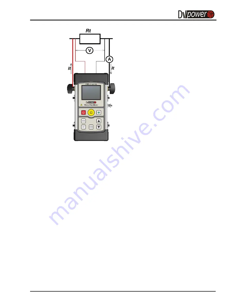
The connection diagram to a one-side grounded circuit breaker is illustrated in the figure below:
With RMO-H turned off, connect RMO-H
to the test object
(
R
t
)
in such a way that
the measuring cables from the "Voltage
Sense" input sockets are attached as
close as possible to the test object R
X
, and
closer to
R
t
than the connection points of
the current feeding cables. That way,
resistance of both, cables and clamps is
almost completely excluded from the
resistance measurement.
Please pay attention to the polarity
while
connecting
the
measuring
cables, otherwise the measurement
results will be incorrect.
Figure 3-1:
Connecting a test
object to RMO-H


