


76
0678106030L02 1411V002
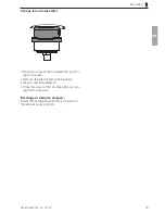
Mounting
• There must be a start-up volume of at least
130 ml between the unit and the non-return
valve�
Exception: The start-up volume is integrated
in the cylinder head as standard in the series
KK 40�
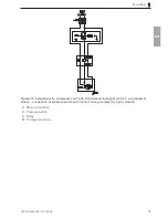
Operating the unit in a system
If the unit is installed in a system, the safety
pressure must not be exceeded (see "4 Techni-
cal data")� It must be ensured that the safety
pressure does not exceed permissible overpres-
sure values by providing of a safety device (e�g�
safety valve, solenoid valve etc�)�
The operating pressure or working pressure
must not exceed the rated pressure of the unit�
Accessories for pressure control e�g� pressure
switches and pressure reducers are necessary
in order to ensure a constant mains pressure
during operation�
Depending on the application, control systems,
valve units, receivers or other accessories are
required for safe operation�
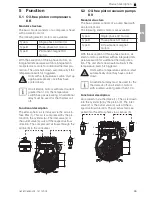
8.3 Connecting oil-free piston
vacuum pumps KV
Suction side
The suction opening is located on the cylinder
head�
The suction opening is indicated by arrows
pointing towards the cylinder head�
• Suction line on the air inlet opening (G 1/4" in-
ternal thread or G1/8" (for KK8)) of the cylin-
der head�
When the unit is shut down, air flows
into the evacuated space�
If this is not wanted, a non-return valve must be
integrated into the suction line� Filters combined
with a non-return valve are available as acces-
sories (see "3�2 Spare parts and accessories")
Exhaust air side
The exhaust air opening is located on the cylin-
der head�
The exhaust air opening is indicated by arrows
pointing away from the cylinder head� A silencer
can be installed (see "3�2 Spare parts and ac-
cessories") in order to reduce the exhaust air
noises�
• Fit a suitable silencer on the exhaust air open-
ing (G 1/4" internal thread) of the cylinder
8 Operation
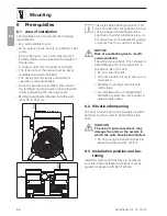
8.1 Remove the transport protec-
tion
For safe transportation, the unit is securely pro-
tected with packaging material�
• Remove the packaging material�
• Remove the protective film�
• Check the unit for damage in transit�
8.2 Connect oil-free piston com-
pressor
The units, depending on the product,
are designed for a specific rated pres-
sure (see "4 Technical data")�
If the rated pressure value is exceeded,
the service life of the products is re-
duced�
The connections for the air inlet and air outlet
are located on the cylinder head� The atmos-
pheric air is drawn in via the air air intake filter
on the air inlet side� On the air outlet side, the
compressed air flows through the air line to the
consumer�
Air inlet
The air inlet opening is located on the cylinder
head� To preserve the service life of the unit, a
suitable air intake filter must be mounted on the
air inlet�
The air inlet opening is indicated by arrows
pointing towards the cylinder head�
• Mount air intake filter on the air inlet opening
(G 1/4" internal thread or G1/8" (for KK8)) of
the cylinder head
Air outlet
The air outlet opening is located on the cylinder
head�
The air outlet opening is indicated by arrows
pointing away from the cylinder head�
• Mount shielded, temperature-resistant com-
pressed-air hose on the air outlet opening (G
1/4" internal thread or G1/8" (for KK8)) of the
cylinder head�
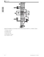
Start-up against pressure
The units will not start up against pressure
• Before the unit is started up, it must always be
purged on the pressure side (e�g� via a me-
chanical vent valve in the pressure switch or
via a solenoid valve)�
EN
Summary of Contents for KK15
Page 2: ......
Page 32: ...30 0678106030L02 1411V002 Product description G1 4 G1 8 Figure 14 KK15 Type A 035 62 EN ...
Page 87: ......