


EN
2012/02
21
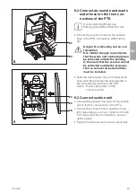
usingacabletie
Leadthecablefrombelow(51)intothecon-
trolunitandconnecttothecontacts(X11
andX12)onthePCB
ForPTSunitswithadisplaypanelthecon-
nectingcableneedstobefedfromabove
intothecontrolunitandthenconnected
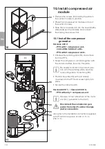
– Dryingunitsventilationfan(M5)andrelief
valve(Y1)
DependingonthemodelofPTStheseare
eitherconnectedtoX1withanadapterca-
bleordirectlyconnectedtoX21andX23
Feedthecablethroughtheconduit(53),se-
curewithcabletieandstrainrelief(52)
OnlyformodelPTS200/03/(230V3~Version)
Fault
Do not connect Power Supply N.
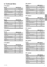
Summary of Contents for PTS 200
Page 1: ...EN 9000 619 14 30 2012 02 Dürr Dental PTS 200 Installation and Operating Instructions ...
Page 2: ......
Page 24: ...EN 24 2012 02 PTS 200 13 Connection media plan 13 1 Set up with VS units ...
Page 25: ...EN 2012 02 25 PTS 200 PC board 13 2 Set up with a display ...
Page 26: ...EN 26 2012 02 PTS 200 13 3 Set up with V units ...
Page 32: ...EN 32 2012 02 400 V 3 part 2 Bleeder valve ...
Page 33: ...EN 2012 02 33 400 V 3 part 3 Display Top Optional Hose manifold con trol switch ...
Page 38: ...EN 38 2012 02 Model type 230V 1 2 aggregates part 3 24 VAC Hose manifold con trol contact ...
Page 47: ......


