background image

10 Adjustment options

10.1 Adjustment of the switch-

on/cut off pressure

WARNING
Risk of explosion of the pressure ves-
sel

The pressure vessels used in the com-
pressors are designed to withstand
continuous pressure changes of 2 bar
and can be used continuously under
these pressure changes.

For load changes > 2 bar (max. per-
missible: 3 bar), comply with the maxi-
mum load change cycles specified in
the operating instructions of the pres-
sure vessel.

The pressure adjustment is performed in standby
mode.

Press the standby button 

 for at least 2 sec-

onds.

Touch the service key 

 for at least 2 sec-

onds.
The blue LEDs in the operating panel flash.
They are touch-sensitive and can be adjusted
accordingly.

The pressure adjustment is performed in
0.5 bar increments by touching the LED.

Touch the first flashing LED with your finger
and swipe to the required 

switch on pressure

.

Touch the last flashing LED with your finger and
swipe to the required 

cut off pressure

.

Confirm with the service key 

.

If no touch pulse is received for 30 sec-
onds, the system will automatically switch
to standby operation. The settings are not
saved.

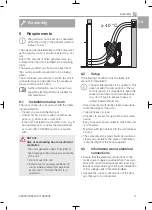
Assembly

26

4252100034L02 2105V002

EN

Summary of Contents for 4152-54

Page 1: ...EN Duo Tandem Quattro Tandem Installation and operating instructions 0297 4252100034L02 4252100034L02 2105V002 ...

Page 2: ......

Page 3: ...sembly 6 Requirements 17 6 1 Installation setup room 17 6 2 Setup 17 6 3 Information about electrical con nections 17 7 Transport 18 8 Installation 18 8 1 Remove the transport locks 18 8 2 Installing the compressor unit 18 8 3 Establishing the compressed air connection 20 8 4 Pressure reducer 20 8 5 Place a collector tray underneath 21 8 6 Network connection 21 8 7 Electrical connections 21 8 8 Tw...

Page 4: ... 13 7 Fault 32 13 8 Emergency mode 32 14 Maintenance 33 14 1 Maintenance schedule 33 14 2 Wear parts and replacement parts 33 14 3 Changing the filter 35 15 Taking out of use 36 15 1 Taking the unit out of use 36 15 2 Storage of the unit 37 Troubleshooting 16 Tips for operators and service techni cians 38 Appendix 17 Handover record 40 Contents 2 4252100034L02 2105V002 EN ...

Page 5: ...rning dangerous high voltage Warning hot surfaces Warning automatic start up of the unit The warnings are structured as follows SIGNAL WORD Description of the type and source of danger Here you will find the possible conse quences of ignoring the warning Follow these measures to avoid the danger The signal word differentiates between four levels of danger DANGER Immediate danger of severe injury o...

Page 6: ...oft tissue can be damaged as a result of careless handling Do not dwell in the area being treated for any longer than is necessary 2 1 Intended purpose The compressor is designed to supply com pressed air for dental applications 2 2 Intended use The air supplied by the compressor is suitable for driving dental tools The compressed air generated by the compres sor is delivered to the pipeline syste...

Page 7: ...ecifi cally approved and authorized by Dürr Dental 2 6 Electrical safety Observe and comply with all the relevant elec trical safety regulations when working on the unit Replace any damaged cables or plugs immedi ately 2 7 Notification requirement of serious incidents The operator patient is required to report any serious incident that occurs in connection with the device to the manufacturer and t...

Page 8: ...with EU Directive 2012 19 EU WEEE If you have any questions about the correct disposal of parts please contact your dental trade supplier An overview of the waste keys for Dürr Dental products can be found in the download area at www duerrdental com Document no P007100155 Important information 6 4252100034L02 2105V002 EN ...

Page 9: ...ription Appliance log book 3 2 Optional items The following items can optionally be used with the unit these items do not bear the CE mark Pressure reducer 6040 992 00 Fine filter 1610 121 00 Wooden cabinet for for sound insulation of Duo Tandem Trio and Quattro Compressors 4251 500 00 3 3 Wear parts and replacement parts The following working parts must be replaced at regular intervals refer also...

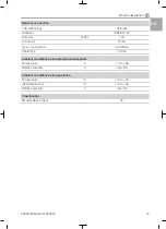
Page 10: ...5 Cut off pressure bar MPa 7 5 0 75 7 5 0 75 Cut off pressure max adjustable bar MPa 9 0 0 9 9 0 0 9 Safety valve maximum permissible oper ating pressure bar MPa 10 1 10 1 Pressure dew point at 7 bar 0 7 MPa C 5 5 Dimensions H x W x D cm 76 x 75 x 52 76 x 79 x 52 Weight kg 70 100 Noise level without sound insulation with sound insulation dB A dB A 66 51 68 50 69 51 72 53 Delivery without membrane ...

Page 11: ...uto MDI X Cable type CAT5 Ambient conditions during storage and transport Temperature C 10 to 55 Relative humidity max 95 Ambient conditions during operation Temperature C 10 to 40 Ideal temperature C 10 to 25 Relative humidity max 95 Classification Medical Device Class IIa Product description 4252100034L02 2105V002 9 EN ...

Page 12: ...e build up phase 0 7 5 bar 0 0 75 MPa c s 190 170 95 85 Duty cycle 100 100 Start up pressure bar MPa 5 5 0 55 5 5 0 55 Cut off pressure bar MPa 7 5 0 75 7 5 0 75 Cut off pressure max adjustable bar MPa 9 0 0 9 9 0 0 9 Safety valve maximum permissible oper ating pressure bar MPa 10 1 10 1 Pressure dew point at 7 bar 0 7 MPa C 5 5 Dimensions H x W x D cm 76 x 75 x 52 76 x 79 x 52 Weight kg 65 95 Noi...

Page 13: ... Type of connection Auto MDI X Cable type CAT5 Ambient conditions during storage and transport Temperature C 10 to 55 Relative humidity max 95 Ambient conditions during operation Temperature C 10 to 40 Ideal temperature C 10 to 25 Relative humidity max 95 Classification Medical Device Class IIa Product description 4252100034L02 2105V002 11 EN ...

Page 14: ...293 516 586 Pressure build up phase 0 7 5 bar 0 0 75 MPa c s 180 160 90 80 Duty cycle 100 100 Start up pressure bar MPa 5 5 0 55 5 5 0 55 Cut off pressure bar MPa 7 5 0 75 7 5 0 75 Cut off pressure max adjustable bar MPa 9 0 0 9 9 0 0 9 Safety valve maximum permissible oper ating pressure bar MPa 10 1 10 1 Pressure dew point at 7 bar 0 7 MPa C 5 5 Dimensions H x W x D cm 82 x 102 x 62 82 x 102 x 6...

Page 15: ...to MDI X Cable type CAT5 Ambient conditions during storage and transport Temperature C 10 to 55 Relative humidity max 95 Ambient conditions during operation Temperature C 10 to 40 Ideal temperature C 10 to 25 Relative humidity max 95 Classification Medical Device Class IIa Product description 4252100034L02 2105V002 13 EN ...

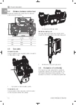
Page 16: ...e plate of the compressor unit is located on the crankcase below the cylinder 1 1 Compressor unit type plate Membrane drying unit The type plate of the membrane drying unit is located on the side of the membrane drying unit 1 1 Membrane drying unit type plate 4 6 Evaluation of conformity This device has been subjected to conformity acceptance testing in accordance with the cur rent relevant Europe...

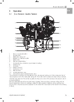
Page 17: ... in atmospheric air and compresses it without oil It then transports the oil free compressed air to the membrane drying unit The cooler and the membrane dryer extract moisture from the compressed air The oil free hygienic and dry air is stored in the pressure tank ready for use in connected devices All of the measurement data for the unit comes together in the control e g pressure in the pressure ...

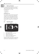
Page 18: ...ating time more or less uniformly between the com pressor units If the compressor is disconnected from the voltage and is then reconnected to the power supply compressor unit 1 will start first again 5 3 Operating panel 1 5 6 2 3 4 1 Fault button with LED 2 Filter replacement button with LED 3 Service key with LED 4 Standby button with LED 5 Pressure range display adjustment 6 Pressure dew point d...

Page 19: ...t damage and or reduced service life of the unit Do not cover the unit Install a fan for auxiliary ventilation in rooms where ambient temperatures exceed 40 C while the unit is in operation 40 C 6 2 Setup The following conditions must be taken into account for installation The air is filtered when it is sucked in This does not alter the composition of the air For this reason it is important to kee...

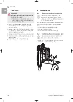
Page 20: ... the transport han dles provided Check the unit for transport damage 8 Installation 8 1 Remove the transport locks The transport locks only need to be removed on the Duo Tandem as the compressor units are delivered separately for the Quattro Tandem For safe transport the appliance is securely pro tected with two foam blocks and a retaining strap Cut and remove the retaining strap Remove the foam b...

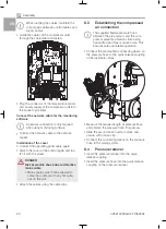
Page 21: ...ne drying unit via the pressure hose Warning risk of dangerous electric vol tages The mains plug must not be plugged in If it is plugged in unplug it Unscrew the fastening screws of the cover for the control NOTICE The operating panel cable is very short and can damage the PCB when the cover is removed Carefully remove the cover of the con trol Unplug the operating panel cable Assembly 4252100034L...

Page 22: ...wed to come into contact with any hot surfa ces on the unit Attach the cables using the cable clips 8 3 Establishing the compressed air connection The supplied flexible pressure hose between the pipe system and the com pressor prevents vibrations from being transmitted and thus reduces noise This ensures safe and reliable operation Connect the premounted connecting sleeve on the pressure hose to t...

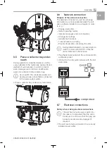
Page 23: ... in order to e g Display parameters Select operating modes Indicate messages and error situations Change unit settings Activate test functions Transmit data for archiving Provide documents concerning the units During initial installation we recommend a router or server with DHCP so that the unit is detected in the network Plug the network cable into the control and into a network socket Connect to...

Page 24: ...ected to each other the controllers of the compressors need to be connected to each other the controllers need to be set up accordingly Connecting pressure vessels If two devices are connected to a single com pressed air network pressure equalisation must take place between the pressure vessels To do this the pressure vessels need to be connected to each other So that the pressure can be equalised...

Page 25: ...handover report is included in the attachment 9 1 Checking the switch on cut off pressure The switch on cut off pressure is preset at the factory Check the adjustment during first start up When the mains plug is connected the compres sor will start after a short delay Read off the cut off pressure from the pressure gauge Drain the air from the pressure tank e g via the condensate drain valve until...

Page 26: ...t off pressure is not taken into account 9 3 Draining the condensation water During transport condensation water can accu mulate in the pressure tank due to changes in temperature This also applies to compressors with a mem brane drying unit At maximum tank pressure slowly open the condensate drain valve Close the condensate drain valve as soon as all of the condensation water has been blown out 9...

Page 27: ...s with other medical devices cannot be completely ruled out Apply the IEC 80001 1 standard for risk assessment The device is not suitable for direct connection to the public Internet Network configuration Various options are available for network configu ration ü Automatic configuration via DHCP recommen ded ü Automatic configuration via Auto IP for direct connection of unit and computer ü Manual ...

Page 28: ...rformed in standby mode Press the standby button for at least 2 sec onds Touch the service key for at least 2 sec onds The blue LEDs in the operating panel flash They are touch sensitive and can be adjusted accordingly The pressure adjustment is performed in 0 5 bar increments by touching the LED Touch the first flashing LED with your finger and swipe to the required switch on pressure Touch the l...

Page 29: ...AH T12AH F5 Fuse T10AH T12AH F6 Fuse T10AH T12AH F7 Fuse T1 6AH H1 Status indicator LED for temperature sensor compressor unit 1 H2 Status indicator LED for temperature sensor compressor unit 1 H3 Status indicator LED for temperature sensor compressor unit 1 H4 Status indicator LED for temperature sensor compressor unit 2 H5 Status indicator LED for temperature sensor compressor unit 2 H6 Status i...

Page 30: ...sor unit 2 X4 Connection compressor unit 1 X5 Connection cooling fan motor membrane drying unit 1 X6 Connection compressor unit 2 X7 Network connection X10 Network connection for connection to main controller auxiliary controller X13 Mains connection X14 Operating panel connection on the control board X15 Connection cooling fan motor membrane drying unit 2 Quattro Tandem only X20 Mains connection ...

Page 31: ... Switch main controller auxiliary controller V1 Solenoid valve 1 V2 Solenoid valve 2 X1 Connection solenoid valve compressor unit 1 X4 Connection compressor unit 1 X5 Connection cooling fan motor membrane drying unit X6 Connection compressor unit 2 X7 Network connection X10 Network connection for connection to main controller auxiliary controller X13 Mains connection 1 N PE AC 230V X14 Operating p...

Page 32: ...rator 4 Dryer 5 Non return valve 6 Pressure tank 7 Compressed air connection 12 2 1 N PE AC 230 V layout 1 1 3 7 8 4 5 6 3 3 2 2 1 Compressor unit 2 Solenoid valve 3 Non return valve 4 Cooler 5 Separator 6 Dryer 7 Pressure tank 8 Compressed air connection Assembly 30 4252100034L02 2105V002 EN ...

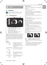
Page 33: ...on and standby mode Pressure range The pressure is displayed and can be adjusted in this area The pressure is displayed via 1 LED 4 5 bar Lights up continuously even with a pressure 4 5 bar e g while the pressure is building up during start up operation 2 10 LEDs 5 9 bar Indicate the pressure status in increments of 0 5 bar 11 LED 9 bar The pressure in the container is too high i e out side the ad...

Page 34: ...ice key to get to set up mode 13 7 Fault The controller monitors the functions of the unit and signals faults according to their importance Faults and warnings can be displayed Faults are triggered as a result of faults in component assemblies or as a result of sensor defects The unit is switched off and the LED of the fault but ton flashes or lights up Fault button LED flashes The fault can be ac...

Page 35: ...humidity is high After approx 1000 operating hours LED on the filter replacement but ton lights up Replace the air intake filter Replace the fine or virus bacteria filter Replace the sintered or coalescence filter In accordance with national law Check the safety valve Carry out recurring safety inspections e g pressure tank inspections electrical safety inspections in accordance with applicable na...

Page 36: ...Information about replacement parts is available from the portal for authorised specialist dealers at www duerrdental net Usage 34 4252100034L02 2105V002 EN ...

Page 37: ...om the mains Press the standby button for at least 2 sec onds Unplug the mains plug Replacing the air intake filter Pull off the noise reducer from the filter Remove the filter Insert a new filter Push on the noise reducer onto the filter 1 2 1 Noise reducer 2 Filters Replacing the fine or virus bacteria filter Unscrew and remove the filter cover Remove the filter Insert a new filter Replace the f...

Page 38: ... compressor is not to be used for a longer period of time it is recommended that the unit be properly shut down and taken out of operation To do so any accumulated condensation water must be drained from the pressure tank and from the drying unit The associated compressor unit must be running to drain the remaining condensa tion water in the water separator of the drying unit Open the condensate d...

Page 39: ...conden sate drain valve pressure tank empty Unplug the mains plug Close the condensate drain valve on the pres sure tank Close condensate drain valves on the drying units Disconnect the compressor from the pipe sys tem 15 2 Storage of the unit WARNING Risk of explosion of the pressure tank and pressure hoses The pressure tank and the pressure hoses must be vented before they are stored or transpor...

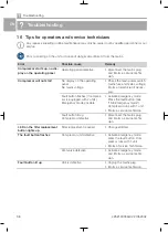
Page 40: ...s sary Fault button flashes if compres sor is equipped with 2 units Emergency mode possible Activate emergency mode Press the fault button see 13 8 Emergency mode Compressor runs with 1 unit Inform a service technician Fault button lit up Compressor defective Disconnect the mains plug and inform a service techni cian LED on the filter replacement button lights up Filter replacement required Change...

Page 41: ...hange in the delivery of the compressor unit Disconnect the mains plug and inform a service techni cian Pressure sensor defective Con tainer pressure is not displayed correctly on the operating panel Compressor blows via the safety valve Disconnect the mains plug and inform a service techni cian Defective relief valve Disconnect the mains plug and inform a service techni cian Compressor switches o...

Page 42: ...name Order number REF Serial number SN o Visual inspection of the packaging for any damage o Unpacking the medical device and checking for damage o Confirmation of the completeness of the delivery o Instruction in the proper handling and operation of the medical device based on the operating instructions Notes Name of person receiving instruction Signature Name and address of the qualified adviser...

Page 43: ...Appendix 4252100034L02 2105V002 41 EN ...

Page 44: ......

Page 45: ......

Page 46: ......

Page 47: ......

Page 48: ...Hersteller Manufacturer DÜRR DENTAL SE Höpfigheimer Str 17 74321 Bietigheim Bissingen Germany Fon 49 7142 705 0 www duerrdental com info duerrdental com ...

Reviews: