


❯
Make sure that none of the electrical cables
leading to the unit are under any mechanical
tension.
❯
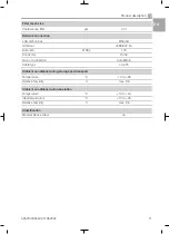
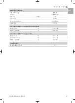
Before initial start-up check that the mains sup-
ply voltage and the voltage stated on the type
plate match (see also "4. Technical data").
Establishing the electrical connections
DANGER
Risk of electric shock due to defective
mains cable
❯
Mains cables must not be allowed to
come into contact with any hot surfa-
ces on the unit.
❯
Connect the mains plug to an earthed power
outlet.
The unit will start immediately when the mains
plug is connected.
❯
Check whether the power outlet is switched via
the surgery main power switch.
This ensures that the unit starts up automati-
cally after the surgery main switch is routinely
switched off and back on again.
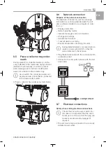
8.8
Two devices in a single com-
pressed air network
With the compressor it is possible for two units to
be connected to a single compressed air net-
work. To do this,
– the pressure vessels need to be connected to
each other;
– the controllers of the compressors need to be
connected to each other;
– the controllers need to be set up accordingly.
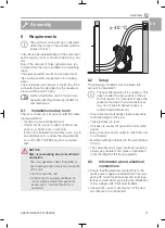
Connecting pressure vessels
If two devices are connected to a single com-
pressed air network, pressure equalisation must
take place between the pressure vessels. To do
this, the pressure vessels need to be connected
to each other.
So that the pressure can be equalised, no
non-return valves must be installed
between the pressure vessels.
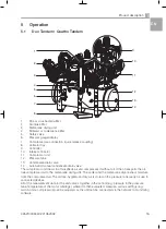
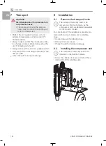
AUX
MAIN
1
Main device (MAIN)
2
Auxiliary device (AUX)
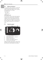
MAIN / AUX for main device / auxiliary device
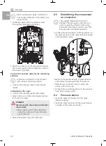
The two electronic controllers of the compressors
are connected to each other via a network cable.
When routing the cables, maintain the
correct gaps between control cables and
supply cables.
❯
Connect the network cable to the network
socket X10.
❯
Guide the cable through the cable holder and
the tension relief and secure it.
❯
Working in the controller of the compressor to
be operated as the primary compressor, check
whether the switch S1 is in the right-hand posi-
tion. If it is not, move it to the right (main con-
trol).
X
S1
X10
Fig. 1: Main controller
Assembly
22
4252100034L02 2105V002
EN


