


5
CAUTION
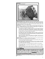
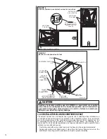
(SEE SECTION 3.2.2: VERTICAL DOWNFLOW & HORIZONTAL RIGHT DISCHARGE )
Unit must be reconfigured for vertical down or horizontal right supply air dis
-
charge applications. The coil must be repositioned so the vertical drainpan is
on the bottom for vertical down discharge applications or the horizontal drip
pan is below coil for horizontal right discharge applications. Failure to recon-
figure the unit for these applications can result in property damage and poor
system performance.
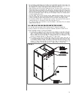
CAUTION
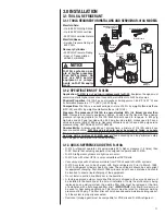
(SEE SECTION 3.3: AUXILIARY OVERFLOW PAN)
In compliance with recognized codes, an auxiliary drain pan must be
installed under all equipment containing evaporator coils that are located in
any area of a structure where damage to the building or building contents
may occur as a result of an overflow of the coil drain pan or a stoppage in
the primary condensate drain piping. See Section 6.3 of this manual for
auxiliary horizontal overflow pan accessory information (model RXBM).
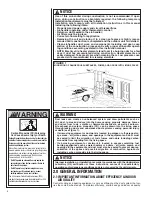
NOTICE
When used in cooling applications, excessive sweating may occur when unit
is installed in an unconditioned space. This can result in property damage.
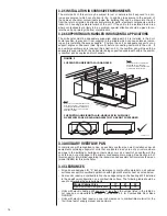
WARNING
(SEE SECTION 3.7: AIR FILTER)
Do not operate the system without filters. A portion of the dust entrained in
the air may temporarily lodge in the duct runs and at the supply registers. Any
circulated dust particles could be heated and charred by contact with the heat-
ing elements. This residue could soil ceilings, walls, drapes, carpets and other
articles in the house.
Soot damage may occur even with filters in place when certain types of can
-
dles, oil lamps or standing pilots are burned.
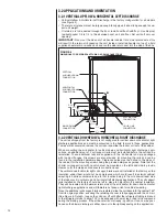
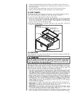
WARNING
The first 36 inches of supply air plenum and ductwork must be constructed
of sheet metal as required by NFPA 90B. The supply air plenum or duct must
have a solid sheet metal bottom directly under the unit with no openings, reg-
isters or flexible air ducts located in it. If flexible supply air ducts are used they
may be located only in the vertical walls of a rectangular plenum, a minimum
of 6 inches from the solid bottom. Metal plenum or duct may be connected
to the combustible floor base, if not, it must be connected to the unit supply
duct flanges such that combustible floor or other combustible material is not
exposed to the supply air opening from the downflow unit. Exposing combus
-
tible (non-metal) material to the supply opening of a downflow unit can cause
a fire resulting in property damage, personal injury or death.
Exceptions to downflow warnings:
• Installations on concrete floor slab with supply air plenum and ductwork
completely encased in not less than 2 inches of concrete (See NFPA 90B).
NOTICE
Improper installation, or installation not made in accordance with the Underwriters
Laboratory (UL) certification or these instructions, can result in unsatisfactory
operation and/or dangerous conditions and are not covered by the unit warranty.
WARNING
PROPOSITION 65:
This appliance
contains fiberglass insulation.
Respirable particles of fiberglass
are known to the State of California
to cause cancer.
All manufacturer products meet
current Federal
OSHA
Guidelines for
safety. California Proposition 65
warnings are required for certain
products, which are not covered by
the
OSHA
standards.
California’s Proposition 65 requires
warnings for products sold in
California that contain or produce
any of over 600 listed chemicals
known to the State of California to
cause cancer or birth defects such
as fiberglass insulation, lead in
brass, and combustion products
from natural gas.
All “new equipment” shipped for
sale in California will have labels
stating that the product contains
and/or produces Proposition 65
chemicals. Although we have not
changed our processes, having the
same label on all our products facil-
itates manufacturing and shipping.
We cannot always know “when,
or if” products will be sold in the
California market.
You may receive inquiries from cus-
tomers about chemicals found in, or
produced by, some of our heating
and air-conditioning equipment, or
found in natural gas used with some
of our products. Listed below are
those chemicals and substances
commonly associated with similar
equipment in our industry and other
manufacturers.
• Glass Wool (Fiberglass) Insulation
• Carbon Monoxide (CO).
• Formaldehyde
• Benzene
More details are available at the
websites for
OSHA
(Occupational
Safety and Health Administration),
at
www.osha.gov
and the State of
California’s OEHHA (Office of
Environmental Health Hazard
Assessment), at
www.oehha.org
.
Consumer education is important
since the chemicals and substanc-
es on the list are found in our daily
lives. Most consumers are aware
that products present safety and
health risks, when improperly used,
handled and maintained.
!
!
!
!
!
!
!


