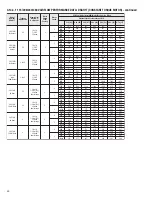
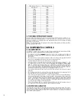
DURASTAR DRAH1T Installation Instructions Manual Download Page 30

30

Model

Number

DRAH1T

Motor

Speed

From

Factory

Tonnage

Application

Blower Size/

Motor H.P.

# of Speeds

Motor

Speed

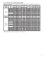
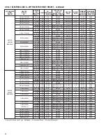
CFM[L/s] Air Delivery/RPM/Watts (Dry Coil – No Filter)

External Static Pressure-Inches W.C.

0.10 [.02] 0.20 [.05] 0.30 [.07] 0.40 [.10]

0.50 [.12] 0.60 [.15] 0.70 [.17]

CFM
RPM
Watts
CFM
RPM
Watts
CFM
RPM
Watts
CFM
RPM
Watts
CFM
RPM
Watts
CFM
RPM
Watts
CFM
RPM
Watts
CFM
RPM
Watts


       1073              1016                963                 906                 854                  —                   —
        637                692                 746                 801                 847                  —                   —
        130                142                 153                 165                 176                  —                   —
         —                 —                    —                  —                  1103               1059               1000
         —                 —                    —                  —                   917                 957                1001
         —                 —                    —                  —                   262                 271                 285
       1044               988                 936                 880                 828                  —                   —
        678                734                 791                 844                 883                  —                   —
        141                155                 158                 171                 182                  —                   —
         —                 —                    —                  —                  1016                961                 904
         —                 —                    —                  —                   939                 968                1015
         —                 —                    —                  —                   233                 243                 265
       1264              1223               1171               1112               1070                 —                   —
        724                761                 814                 868                 900                  —                   —
        198                208                 222                 237                 245                  —                   —
         —                 —                    —                  —                  1288               1244               1200
         —                 —                    —                  —                   974                1012               1044
         —                 —                    —                  —                   345                 362                 371
       1233              1193               1142               1084               1042                 —                   —
        750                794                 845                 915                 933                  —                   —
        219                215                 227                 251                 261                  —                   —
         —                 —                    —                  —                  1257               1213               1169
         —                 —                    —                  —                  1020               1023               1054
         —                 —                    —                  —                   355                 368                 376

4

5

3621AM

with

18kW Heater

5

10x10

1/2 HP

5 Speed

4

5

3 & 3.5

3621AM

No Heater

3621AM

No Heater

3621AM

with 18kW

Heater

5

5

5

10x10

1/2 HP

5 Speed

10x10

1/2 HP

5 Speed

10x10

1/2 HP

5 Speed

2

3

2.5

2.5

3 & 3.5

3

2

CFM
RPM
Watts

CFM
RPM
Watts

CFM
RPM
Watts

CFM
RPM
Watts

CFM
RPM
Watts

3621AH
No Heat

5

10x10

1/2 Hp [373]

2 Speed

dual voltage

2

3621AH

18 kW Heat

5

10x10

1/2 Hp [373]

2 Speed

dual voltage

2

5

10x10

1/2 HP [373]

2 Speed

dual voltage

4

5

5

10x10

1/2 Hp [373]

2 Speed

dual voltage

4

3621AH
No Heat

3621AH

18 kW Heat

2.5

2.5

3

3

CFM
RPM
Watts

3

       1305              1251               1205               1154               1101               1046                995
        668                727                 752                 797                 832                 888                 914
        193                187                 183                 208                 210                 213                 247

       1249              1193               1138               1082               1026                970                 914
        732                780                 828                 877                 925                 973                1021
        114                123                 133                 142                 151                 161                 170

CFM
RPM
Watts

3

       1280              1228               1176               1124               1072               1020                968
        695                736                 777                 817                 858                 899                 939
        189                191                 197                 208                 223                 243                 267

       1221              1166               1110               1054                998                 942                 886
        756                804                 853                 901                 949                 997                1045
        119                128                 137                 147                 156                 165                 175

       1468              1421               1377               1332               1285               1240               1192
        739                773                 822                 863                 901                 937                 974
        238                268                 276                 307                 313                 302                 297

       1272              1220               1174               1124               1067               1016                961
        658                706                 753                 797                 838                 877                 925
        180                189                 189                 190                 225                 202                 246

CFM
RPM
Watts

5

       1445              1399               1354               1308               1262               1216               1170
        759                799                 839                 878                 918                 958                 997
        252                277                 295                 305                 308                 303                 290

       1249              1197               1145               1093               1042                990                 938
        684                728                 772                 816                 859                 903                 947
        183                186                 192                 202                 214                 230                 248

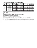
3.14.3.1  115/208/240/480V AIRFLOW PERFORMANCE DATA: DRAH1T (CONSTANT TORQUE MOTOR) - continued

Summary of Contents for DRAH1T

Page 1: ...nstallation adjustment and operation of this unit Read these instructions thoroughly before attempting installation or operation Failure to follow these instructions may result in improper installatio...

Page 2: ...factured Homes 15 3 2 5 Installation in Corrosive Environments 16 3 2 6 Supporting Air Handler in Horizontal Applications 16 3 3 Auxiliary Overflow Pan 16 3 4 Clearances 16 3 5 Duct Flanges 17 3 6 Duc...

Page 3: ...5 4 6 Checking Indoor Air Flow 35 4 6 1 Estimating CFM Using External Static Pressure 35 4 6 2 Estimating CFM Using Electric HEat Temperature Rise 35 4 7 Checking Refrigerant Charge 36 5 0 COMPONENTS...

Page 4: ...aled to prevent depres surization of the space and possible migration of combustion byproducts including carbon monoxide into the living space WARNING SEE SECTION 3 6 DUCTWORK Do not under any circums...

Page 5: ...d to the supply air opening from the downflow unit Exposing combus tible non metal material to the supply opening of a downflow unit can cause a fire resulting in property damage personal injury or de...

Page 6: ...e in place Correct air flow setting for application Removing the coil and storing it in a clean safe place is highly recom mended until construction is completed and the outdoor unit is installed Clea...

Page 7: ...IVED Immediately upon receipt all cartons and contents should be inspected for transit dam age Units with damaged cartons should be opened immediately If damage is found it should be noted on the deli...

Page 8: ...y secure the third lead The air handlers are shipped from the factory with the proper indoor coil installed and cannot be ordered without a coil These air handlers do not have an internal filter rack...

Page 9: ...ID LINE CONNECTION COPPER SWEAT VAPOR LINE CONNECTION COPPER SWEAT 2111 16 105 16 SUPPLY AIR W A H 191 2 RETURN AIR OPENING SEE DUCT FLANGES SECTION 3 5 FOR INSTRUCTIONS DIMENSIONAL DATA MODEL SIZE RE...

Page 10: ...NT This product has been designed and manufactured to meet certified AHRI capacity and efficiency ratings with the appropriate outdoor units However prop er refrigerant charge proper airflow and refri...

Page 11: ...performed safely with nitrogen or a mixture of R 410A and nitrogen 3 1 3 QUICK REFERENCE GUIDE FOR R 410A R 410A refrigerant operates at approximately 60 higher pressure 1 6 times than R 22 Ensure th...

Page 12: ...n the sides of the cabinet for the mounting screws using the provided dimples as guides Note that the shorter coil support rail with no notch must be mounted on the left hand side to provide clearance...

Page 13: ...nsulation is caught in lug Tighten lug as tight as possible while holding circuit breaker Check wires and make sure each wire is secure and none are loose Repeat for left wire bundle in left top circu...

Page 14: ...rec ommended for all air handler applications but special attention should be paid to those installed in unconditioned spaces Duct sizing and airflow are critical and must be based on the equipment se...

Page 15: ...ing or a restricted coil drain line See Section 3 3 If an electric heater kit is installed be sure the breaker or disconnect cover is sealed tightly to the door panel 3 2 4 INSTALLATION IN MOBILE MANU...

Page 16: ...ent containing evaporator coils that are located in any area of a structure where damage to the building or building contents may occur as a result of an overflow of the coil drain pan or a stoppage i...

Page 17: ...that the system airflow be adequate Make sure supply and return ductwork grills filters accessories etc are accounted for in total resistance Refer to the airflow performance tables in this manual to...

Page 18: ...nded orifice size for various outdoor units Piston size installed at factory Correct piston for other tonnages will be included with the matching outdoor unit 3 9 REFRIGERANT LINE CONNECTIONS CHARGING...

Page 19: ...lation should be pulled back in place so it contacts the air handler cabinet to prevent condensate from forming on the cold tube and dripping off A loosely fitting zip tie placed around the insulation...

Page 20: ...t block service access to front of the unit Minimum clearance of 24 inches is required for filter coil or blower removal and service access Although the condensate drain pan is designed is designed to...

Page 21: ...d drain line after installation is complete Pour water into drain pan enough to fill drain trap and line Check to make sure drain pan is draining completely no leaks are found in drain line fittings a...

Page 22: ...the event of a short circuit and serve as a disconnect Circuit breakers installed within the unit do not provide over current protection of the supply wiring and therefore may be sized larger than th...

Page 23: ...0 35 RXBH 1724A13C 9 4 12 5 3 60 3 4 17 SINGLE 26 1 30 1 1 6 35 40 35 40 3617AS 208 240V RXBH 17 03J 2 25 3 0 1 60 1 3 0 SINGLE 10 8 12 5 2 8 17 20 20 20 3617AS 3621AM 3621AH 208 240V RXBH 1724 03J 2...

Page 24: ...0 0 32 37 35 40 RXBH 1724 05J 3 6 4 8 1 60 1 4 8 SINGLE 17 3 20 0 4 6 28 31 30 35 RXBH 1724 07J 5 4 7 2 1 60 2 3 6 SINGLE 26 0 30 0 4 6 39 44 40 45 RXBH 1724 10J 7 2 9 6 1 60 2 4 8 SINGLE 34 6 40 0 4...

Page 25: ...or load is included in single circuit or circuit 1 of multiple circuits Heater loads are balanced on 3 phase models with 3 or 6 heating elements only Electric heater kits are not permitted for use wit...

Page 26: ...wiring where the breakers apply has been UL approved for short circuit protection Ampacity not breaker size determines supply circuit wire size The ampacity listed on the unit rating plate and the Ma...

Page 27: ...performance operate the unit in the 3 to 7 in W C external static range Units should be applied with a minimum of 1 in W C external static pressure NOTE The air flow performance data tables see Sectio...

Page 28: ...Speed tap T1 is always dedicated to continuous fan operation and delivers approximately 50 of the speed tap T4 air flow Speed taps T2 T4 are for applications with an external static pressure up to 0...

Page 29: ...96 1017 480 977 461 935 441 671 725 764 809 852 153 168 174 180 188 1084 512 1040 491 1001 472 896 936 971 249 257 261 1068 504 1025 484 992 468 952 449 910 429 711 765 804 849 892 164 179 185 191 199...

Page 30: ...5 3 2 CFM RPM Watts CFM RPM Watts CFM RPM Watts CFM RPM Watts CFM RPM Watts 3621AH No Heat 5 10x10 1 2 Hp 373 2 Speed dual voltage 2 3621AH 18 kW Heat 5 10x10 1 2 Hp 373 2 Speed dual voltage 2 5 10x1...

Page 31: ...1x11 3 4 559 5 Speed 11x11 3 4 559 5 Speed 11x11 3 4 559 5 Speed 4 5 2 3 2 3 6024AS No Heater 6024AS with 30kW Heater 6024AS No heater 6024AS with 30kw heater CFM RPM Watts CFM RPM Watts 1625 767 1591...

Page 32: ...4 1069 374 379 386 396 408 423 440 1465 1423 1381 1338 1296 1254 1212 779 816 854 891 929 967 1004 257 270 281 287 290 289 285 CFM RPM Watts 5 1803 1760 1217 1683 1648 1612 1576 886 919 952 988 1019 1...

Page 33: ...and Y inputs from the thermostat are de energized A time delay programmed into the DRAH1T motor keeps the blower motor energized for an additional 30 seconds to extract the residual cooling from the c...

Page 34: ...o provide a 3rd stage of heat as needed When the thermostat call is satisfied The G and Y terminals inputs from the thermostat are de energized A time delay programmed into the DRAH1T motor keeps the...

Page 35: ...ss the filter is accounted for The static pressure inside the supply plenum should be measured at a point about half way between the air handler and the first elbow or the end of the plenum Total exte...

Page 36: ...eration T2 T5 are for cooling heating operation and are selectable at the terminal block using a single wire with an insulated terminal that plugs onto the terminals in the ter minal block Speed chang...

Page 37: ...s through the blower access door The blower slides into place on a track and is secured by 4 sheet metal screws 5 5 TRANSFORMER A 40VA transformer is located inside the control box attached to the blo...

Page 38: ...e are no C Voltage air handlers available C voltage heater kits are for 3 phase applications and allow for smaller wire fuse breaker size compared to single phase J Voltage heater kits The heater kit...

Page 39: ...he system filter every ninety days or as often as found to be necessary and if obstructed clean or replace at once A qualified installer service agency or HVAC professional should instruct the homeown...

Page 40: ...mild solvent such as hot water and detergent Be careful not to disturb the balance weights clips on the blower wheel blades Do not drop or bend wheel as balance will be affected 7 4 MOTOR LUBRICATION...

Page 41: ...een the inlet orifice and outside of blower wheel Tighten setscrew on motor shaft Turn wheel by hand to make sure it runs true without hitting blower sides Reassemble motor wiring to capacitor and mot...

Page 42: ...V WULSSHG FKHFN IRU ORZ DLU IORZ 2YHU WHPSHUDWXUH OLPLW KDV IDLOHG UHSODFH 6HTXHQFHU RU FRQWDFWRU KDV IDLOHG UHSODFH 2QH RU PRUH KHDWLQJ HOHPHQWV KDYH EXUQHG RXW UHSODFH RLO LV IUR HQ XS 6 VWHP ORZ RQ...

Page 43: ...43 9 0 WIRING DIAGRAMS 9 1 WIRING DIAGRAM DRAH1T 208 240V 3 0 3 0 2 0 0 0 1 0 2 0 0 0 1 0...

Page 44: ...44 CM 0720...

Reviews: