


16
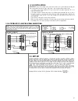
3.2.5 INSTALLATION IN CORROSIVE ENVIRONMENTS
The metal parts of this unit may be subject to rust or deterioration if exposed to a cor-
rosive environment which can shorten its life. In addition to exposure to the exterior of
the cabinet, chemical contaminants inside the building that can be drawn into the unit
from the return air grille and attack structural metal parts, electrical components and the
indoor coil, causing premature failure of the unit. If the unit is to be installed in an area
where contaminants are likely to be a problem, special attention should be given to iso-
late the unit and return grille from contaminants.
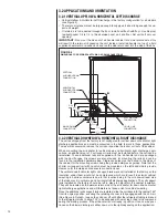
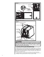
3.2.6 SUPPORTING AIR-HANDLER IN HORIZONTAL APPLICATIONS
The air-handler must be adequately supported underneath if it is installed in the hori-
zontal position to prevent it from sagging in the middle which can cause issues remov-
ing and re-installing the access panels. Position the unit on adequate supports or on
support angles or channels (See Figure 9) before connecting ductwork to the unit. If
an auxiliary overflow pan is required (See Section 3.3), the overflow pan will need to be
adequately supported with the air-handler being supported underneath within the auxilia-
ry overflow pan by angles and/or channels.
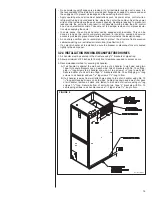
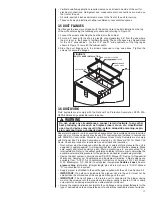
3.3 AUXILIARY OVERFLOW PAN
I
n compliance with recognized codes, an auxiliary overflow pan must installed under all
equipment containing evaporator coils that are located in any area of a structure where
damage to the building or building contents may occur as a result of an overflow of the
coil drain pan or a stoppage in the primary condensate drain piping. See Section 6.3 of
this manual for information regarding the recommended auxiliary horizontal overflow pan
(model RXBM) for this air-handler.
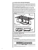
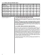
3.4 CLEARANCES
• All units are designed for “0” inches clearance to combustible material on all cabinet
surfaces except for downflow application with higher kW electric heat as noted below.
• Some units require a combustible floor base depending on the heating kW if installed
in the downflow configuration on a combustible surface. The following table should be
used to determine these requirements.
• Units with electric heating kW equal to or less than the values listed in the table do
not require a combustible floor base. See Section 6.5 for Combustible Floor Base
RXHB-XX.
• Units with electric heat require a one inch clearance to combustible material for the
first three feet of supply plenum and ductwork.
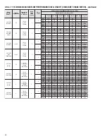
Model Cabinet Size
17
21
24
Maximum Model Designation kW
15
18
20
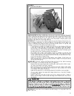
SUPPORTING HORIZONTAL AIR-HANDLERS IN AUXILIARY
OVERFLOW PANS OR AIR-HANDLERS THAT ARE NOT SUSPENDED.
NOTE:
DO NOT BLOCK AIR-HANDLER ACCESS
WITH SUPPORT RODS, ALLOW SPACE
FOR PROPER SERVICE MAINTENANCE
OR REPLACEMENT OF THE COIL AND
BLOWER ASSEMBLY.
NOTE:
HORIZONTAL LEFT ORIENTATION
DEPICTED IN ILLUSTRATION.
HORIZONTAL RIGHT ORIENTATION
IS SIMILAR IN INSTALLATION.
SUSPENDED HORIZONTAL AIR-HANDLER.
AIR FL
OW
ST-A1298-01
FIGURE 9


