


18
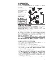
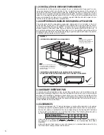
3.7 RETURN AIR FILTER
An internal filter rack is not provided with this air-handler. Therefore, an external means
of filtering the return air is required. External filters should be sized for a maximum of
300 feet/min air velocity or the maximum velocity recommended by the type of filter
installed. One or more return air filter grilles, a filter rack attached to unit return air
intake, or a filter rack installed between a sealed return air platform and the return duct
are all acceptable means of filtration. All return ducts must be filtered, either at each
return grille or at a common filter near the unit.
Important:
Do not install a return air filter grille
and
a filter rack at the unit and do not
install a filter in the supply duct system.
Filter type, sizing, and placement are critical to heating and cooling system performance.
Reduced air-flow can shorten the life of system components such as the compressor,
indoor coil, heater elements, over temperature limits, and relays. As filters near the end
of their useful life, the pressure drop through them increases. Therefore, it is important
to factor the “end of life” (dirty) pressure drop of filters into the external static pressure
of the duct system when selecting blower speeds and designing ductwork to assure
the system is operating at the design CFM and system reliability is not compromised.
Always verify that the system’s air-flow is within specifications by performing a tempera-
ture rise (heating mode) and/or temperature drop (cooling mode) with all filters in place.
Important:
High efficiency pleated filters and electronic air cleaners typically have
significantly higher pressure drop than standard efficiency fiberglass filters, especially
when they get dirty. Do not use high efficiency filters or electronic air cleaners unless
adequate filter area is provided to lower the filter pressure drop to an acceptable level.
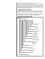
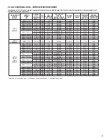
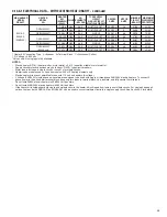
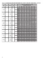
3.8 ORIFICE SIZE
The piston model air handler comes standard with a flow check piston installed. The pis-
ton may need to be changed to a different orifice size depending upon the outdoor unit.
The following table lists the recommended orifice size for various outdoor units.
*Piston size installed at factory. Correct piston for other tonnages will be included with
the matching outdoor unit.
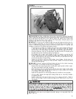
3.9 REFRIGERANT LINE CONNECTIONS & CHARGING
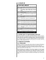
3.9.1 PREPARATION
The coil is shipped with a low pressure (5-10 psig) charge of dry nitrogen which will be
released when the rubber plugs are removed. Leave the rubber plugs in the refrigerant con-
nection stubs on the air-handler until the refrigerant lines are ready to be brazed to the refrig-
erant connection stubs to prevent contaminants from entering the coil. Clean the ends of the
tubing and coil connection stubs (inside and outside) with an alcohol wipe before inserting
the line set tubes into the coil connection stubs to assure a quality leak-free braze joint.
Refer to the outdoor unit installation instructions for details on refrigerant line sizing and
installation. Be sure to follow long line length guidelines if they apply.
Route the refrigerant tubing in a manner than does not block service access to the front
of the air-handler.
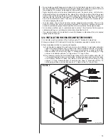
3.9.2 LIQUID LINE FILTER DRIER
A new liquid filter drier must be installed every time any part of the system has been
open to the atmosphere, even if it’s for a short period of time. The filter drier should be
installed close to the air-handler for a system started up in the cooling mode and near
the outdoor unit for a heat pump system started up in the heating mode. This allows the
filter drier to catch any contaminants in the liquid line before they can enter the indoor or
outdoor TXV inlet screen.
2417
1
1
⁄
2
Ton
R-410A .049
2 Ton
.057*
3617
2
1
⁄
2
Ton
R-410A
.062
3 Ton
.067*
4821
3
1
⁄
2
Ton
R-410A
.074
4 Ton
.078*
Indoor
Nominal Tons
Refrigerant
Piston
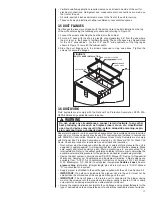
!
WARNING
Do not operate the system without filters. A portion of the dust entrained in
the air may temporarily lodge in the duct runs and at the supply registers.
Any circulated dust particles could be heated and charred by contact with the
heating elements. This residue could soil ceilings, walls, drapes, carpets and
other articles in the house. Operating the system without a filter will also allow
lint and dirt particles to accumulate on the indoor coil fin and restrict air-flow
through the coil. Soot damage may occur even with filters in place when cer
-
tain types of candles, oil lamps or standing pilots are burned.


