Start-up Manual
89475/119 ETM
44
Duplomatic MS S.p.A.
All rights reserved.
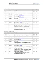
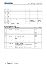
Description of the Control_3
Nr.
Bit
Name
Description
Type
Default
1
0
LIVEBIT
Here the controller can provide an alternating input signal in
order to monitor the funtioning of the bus connection.
It will be returned by the output “LIVEBIT_OUT”.
BOOL
0
2
1
-
-
BOOL
0
3
2
-
-
BOOL
0
4
3
-
-
BOOL
0
5
4
-
-
BOOL
0
6
5
-
-
BOOL
0
7
6
SC
Synchronous control.
In synchronous run the preset values for axis 2 are not active.
The system is driven by the demand values of axis 1.
BOOL
0
8
7
Direct
In direct mode new command positions are taken over directly
from the controller while the START signal is available.
In normal mode the START signal has to be reset and set again
for activating a new command position.
BOOL
0
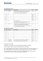
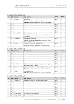
Description of the Control_4
Nr.
Bit
Name
Description
Type
Default
1
0
-
-
BOOL
0
2
1
-
-
BOOL
0
3
2
-
-
BOOL
0
4
3
-
-
BOOL
0
5
4
-
-
BOOL
0
6
5
-
-
BOOL
0
7
6
PARAVALID
Transmitting a new parameter setting (at rising edge).
BOOL
0
8
7
PARAMODE
Enables parameterizing the controller via fieldbus
BOOL
0
Description of the LIVEBIT
The fieldbus communication can be monitored with the LIVEBIT functionality.
If this bit is set to "TRUE", an internal monitoring function is activated.
After a single triggering of this control bit, a permanent change of the value must take place. It is
monitored cyclically that this input value is changed at least once per second by the fieldbus.
After expiration of this time without data change the READY state of the module is exited.
The state of the bit is continuously re-ported back via LIVEBIT OUT.

