2
.
0 INSTALLATION
2.1 FOUNDATION
A flat, level concrete foundation or floor capable
of supporting the weight of the unit must be
provided. Weights are given in Table 2.1. The
unit must be leveled to within 1/16" per foot
[5.2mm per meter] for proper operation.
2.2 VIBRATION
ISOLATION
In case of structure-borne vibration may be of
concern, it is recommended that the unit be
mounted on vibration isolators. Rubber-in-shear
isolators or spring isolators are available for this
unit as optional equipment. If spring isolators are
installed, it is also necessary to provide isolation
in condenser water and chilled water pipes by
means of flexible connectors and in main power
supply conduit through use of flexible conduit.
Isolation of piping and electrical conduit is
desirable in any event, to avoid noise transmission.
2.3 UNMOUNTED
ACCESSORIES
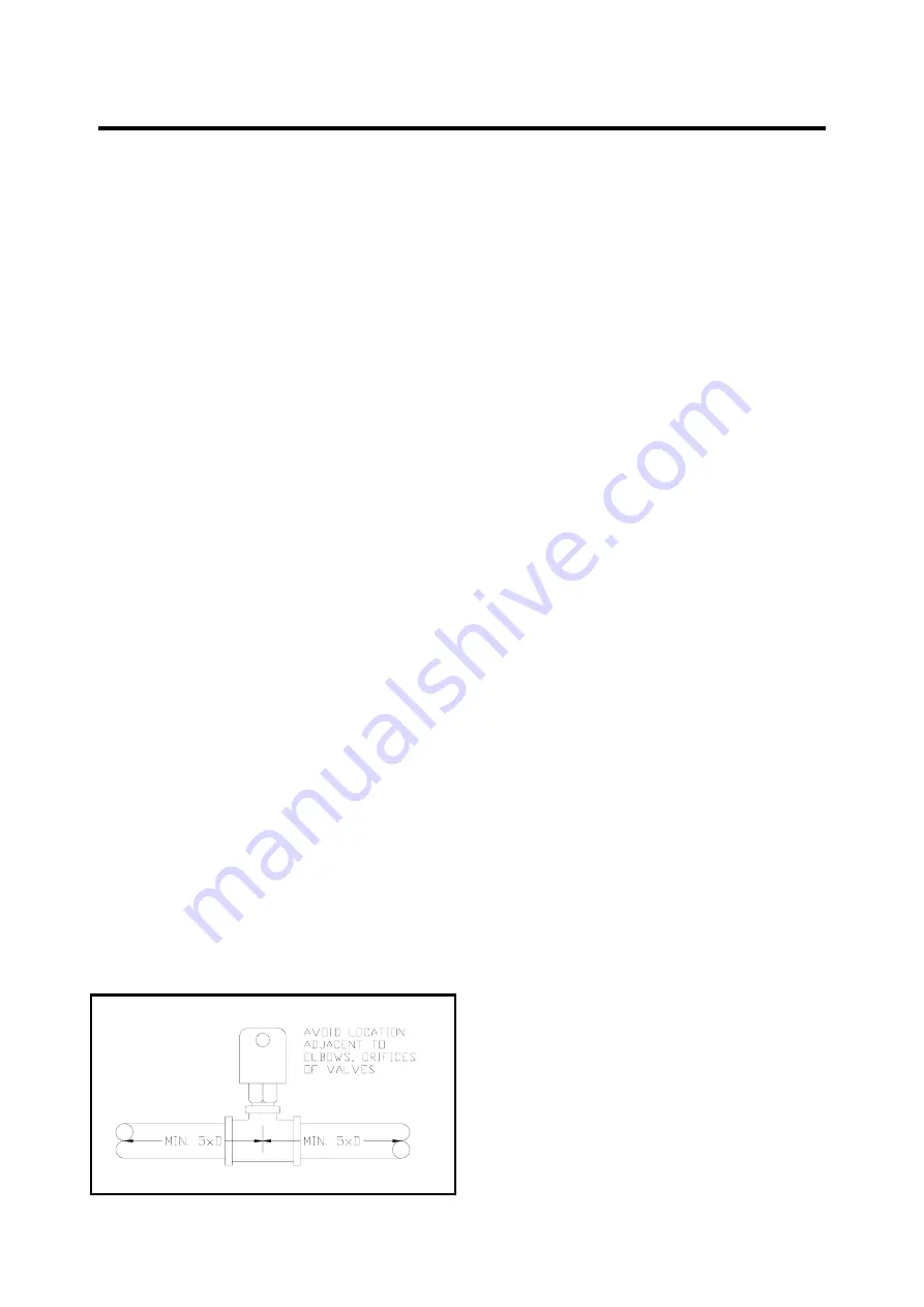
A chiller flow switch, which is shipped in a
separate container accompanying the unit, must
be installed in the external chilled water outlet
piping. It must be located in a horizontal section
on the pipe where there is at least five (5) pipe
diameters on both sides of the flow switch before
any other connections, as indicated in Fig. 1. The
flow switch paddle must be adjusted to the size of
pipe in which the paddle is installed, and the
switch set to trip at approximately 50% of the
design flow. Consult the wiring diagram
accompanying the unit for the electrical
connections to interlock the flow switch with the
control panel.
FIGURE 2.3 FLOW SWITCH
2.4 WATER PIPING
CONNECTIONS
Refer to Figures 1.3. for water piping connection
locations. Note that the condenser water inlet
must be on the bottom. If necessary, evaporator or
condenser headers can be reversed, left to right or
vice versa. Leaving chilled water temp sensor
must be located in leaving chilled water stream.
After the unit has been leveled and isolators (if
any) has been installed and adjusted, evaporator
and condenser water piping are connected. Piping
must be properly supported to avoid stress on unit
water connections. Install air vent valves in all
high connections on evaporator and condenser
headers. Drain valves shall be installed in similar
low points to facilitate gravity draining of the
system. It is important that water systems should
be cleaned before start-up to avoid collecting
debris in evaporator and condenser. The best
solution is to install wye strainers in both systems
upstream of the unit. After the systems are filled
with water, trapped air shall be bled from the
various vent valves. Check for proper flow rates
by measuring water pressure drop across heat
exchangers and reading flow rates from charts,
Figure 2.4. Compare measured flow rates with
values specified on purchase order. Check in
Table 2.1. to see that evaporator and condenser
flow rates fall between min. and max. limits.
2.5 ELECTRICAL
WIRING
In connecting power wiring to the unit, the
following precautions should be taken:
- All field wiring shall be in accordance with the
National Electric Code and must comply with
state and local codes.
- Check unit wiring for damage and all terminal
connections for tightness. Unit terminal blocks
are connected with copper conductors only,
and are sized according to ampacity listed on
unit data plate.
- Connections to unit should match the unit
name plate in volts, phase and Hertz. Voltage
must not vary beyond ±10% of name plate
value and voltage imbalance between phases
must not exceed 2% at any time during
operation of the unit.
- Phase sequence to connections L1, L2, L3
shall be in that order. Check with Amprobe
phase sequence adapter PSA-1 or equivalent.
- 10 -
Summary of Contents for WCFX 10
Page 8: ...TWO PASS RIGHT HAND ARRANGEMENT SHOWN 1 0 GENERAL INFORMATION WCFX 20 22 24 27 30 33 36 8...
Page 9: ...1 0 GENERAL INFORMATION WCFX 39 42 45 48 51 54 9...
Page 31: ...3 0 OPERATION FIGURE 3 5 PIPING SCHEMATIC 1 1 COMPRESSOR WCFX 10 12 15 18 31...
Page 32: ...3 0 OPERATION 2 2 COMPRESSORS WCFX 20 22 24 27 30 36 32...
Page 33: ...3 0 OPERATION 3 3 COMPRESSORS WCFX 39 42 45 48 51 54 33...
Page 36: ...4 0 ELECTRICAL FIGURE 4 2 TYPICAL WIRING SCHEMATIC A 1 COMPRESSOR 36...
Page 37: ...4 0 ELECTRICAL 37...
Page 38: ...4 0 ELECTRICAL B 2 COMPRESSORS 38...
Page 39: ...4 0 ELECTRICAL 39...
Page 40: ...4 0 ELECTRICAL 40...
Page 41: ...4 0 ELECTRICAL C 3 COMPRESSORS 41...
Page 42: ...4 0 ELECTRICAL 42...
Page 43: ...4 0 ELECTRICAL 43...
Page 44: ...4 0 ELECTRICAL 44...


