background image

www.factorybuysdirect.com

200423-01A

32

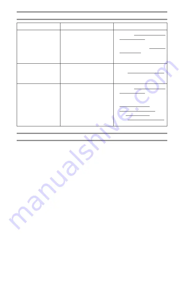
TROUBLESHOOTING

Problem

Possible Cause

Corrective Action

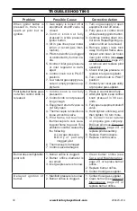
Fireplace shuts off in use. 1. Not enough fresh air is avail

-

able. 

2. Gas leak See 

Warning State-

ment 

at the top of the page 

29. 

3. Low fuel supply.

1. Refer to Air for Combustion 

and Ventilation, page 7. 

2. Contact local gas supplier. 

3.  Clean  pilot  (see 

Care and 

Maintenance

, page 27)

4. Refill supply tank (propane 

tank).

Gas  odor  exists  even 

when control knob is in 

OFF position. 

1. Gas  leak.  See 

Warning 

Statement 

at top of page 29.

2. Control valve is defective.

1. Locate and correct all leaks 

(see 

Care and Maintenance

page 27)

2. Contact customer service.

Soot appearing on logs 

or upper mantel facing.

1. Not  enough  combustion/ 

ventilation in the air.

2. Damaged or misplaced logs 

or debris in burner media.

3. Excessively sustained high 

winds. 

1. Refer to Air for Combustion 

and Ventilation, page 7.

2.  Correct  log  position  or  re

-

place  damaged  logs  (see 

Inspecting Burners

, page 25, 

Installing Glass Media

, page 

22, 

Installing Logs

, page 23

3. See 

Locating the Fireplace

page 8

REPLACEMENT PARTS

Note: Use only original replacement parts. This will protect your warranty coverage for parts 

replaced under warranty.

PARTS UNDER WARRANTY 

Contact  authorized  dealers  of  this  product. 

If  they  can’t  supply  original  replacement 

parts,  call  Customer  Service  toll  free  at


1-855-607-6557

 for referral information.

When  calling  Customer  Service  or  your 

dealer, have ready:
•  Your name
•  Your address

•  Model and serial number of your heater
•  How heater was malfunctioning
•  Type of gas used (Propane or Natural gas)
•  Purchase date
•  Usually, we will ask you to return the defec

-

tive part to the factory

PARTS NOT UNDER WARRANTY

Contact  authorized  dealers  of  this  product. 

If  they  can’t  supply  original  replacement 

part(s)  call  Customer  Service  toll  free  at


1-855-607-6557

 for referral information.

When calling Customer Service have ready:
•  Model number of your heater
•  The replacement part number

Summary of Contents for DF450SS-G

Page 1: ...ther appliance WHAT TO DO IF YOU SMELL GAS Shut off gas to the appliance Extinguish any open flame If odor continues keep away from the appliance and immediately call your gas supplier or the fire department Installation and service must be performed by a quali fied installer service agency or the gas supplier Questions problems missing parts Before returning to your retailer call our customer ser...

Page 2: ...placement Parts 32 Parts 33 Accessories 35 Warranty 36 INSTALLER Leave this manual with the appliance CONSUMER Retain this manual for future reference WARNING Improper installation adjustment al teration service or maintenance can cause injury or property damage Read the installation operating and maintenance instructions thoroughly before installing or servicing the equipment This appliance is on...

Page 3: ...vided should be closed when burner is in use This appliance must not be installed indoors or within any structure that prevents or inhib itstheexhaustgasfromdissipat ing in the outside atmosphere SAFETY IMPORTANT Readthisowner s manualcarefullyandcompletely before trying to assemble op erate or service this heater Improper use of this heater can cause serious injury or death from burns fire explos...

Page 4: ...appliance where it will be shielded and not subject to high winds See Locating the Fireplace page 8 8 Always operate fireplace with control knob in either the PILOT IGN or full on position Never continuously operate the fireplace at lower than full ON position Lower flame rate may produce high levels of sooting and flame outage 9 Do not use appliance if any part has been under water Immediately ca...

Page 5: ...ls DF450SS G and DF450SS L Ignition Electronic Ignitor Gas Type Natural Propane when converted Maximum Input Rating 24 000 BTU Hr 24 000 BTU Hr Regulator Pressure Setting 6 W C 6 W C Main Burner Orifice Size 2 05 mm 1 66 mm Inlet Gas Pressure inches of water Max 10 5 W C Max 13 W C Normal 7 W C Normal 11 W C Min 6 5 W C Min 8 W C Fireplace Weight 84 5 lbs Shipping Weight 92 5 lbs Assembled Dimensi...

Page 6: ...Remove the top carton tray and 4 corner supports 3 Remove the outer carton and upper foam packing containing the 4 standoff brack ets with hardware Retain standoffs and hardware pack for later installation 4 Remove the box containing the front frame assembly and hardware kit Set aside for later installation 5 Lift the fireplace out of the bottom foam packing and lower carton trays Instal lation ma...

Page 7: ...om the forward openings on the bottom of the fireplace The installation must provide a way to drain the water from the base of the unit by building or installing a raised platform with openings positioned under the drain area Additional space below the unit will also required a drain opening to allow the water to drain from the enclosure When installed on exterior walls the fireplace cabinet shoul...

Page 8: ... enclosure with walls on all sides but at least one permanent opening at ground level and no overhead cover Within a partial enclosure that includes an overhead cover and no more than two walls Within a partial encloser that includes an overhead cover and more than two walls the following shall apply At least 25 of the total wall area is com pletely open and At least 30 of the remaining wall area ...

Page 9: ...eight 20 3 8 E Firebox Viewing Depth 25 3 4 F Floor to Firebox Opening 6 7 8 G Recessed Unit Width 26 1 8 H Width of Nailing Standoffs 27 5 8 I Height to Nailing Standoffs 29 J Floor to Gas Inlet 3 K Side to Gas Inlet 3 1 4 L Depth from Back to Gas Inlet 1 1 4 M Standoff Clearances 3 4 N Front Frame Depth 3 4 G L C N M M A D F I E B H Top Right Side Front Back J K ...

Page 10: ...ls Materials consisting entirely of steel iron brick tile concrete slate glass or plasters or any combination there of are suit able Materials that are reported aspassingASTME136 standard test method for behavior of ma terials in a vertical tube furnace at1382F 750C andUL763shall be considered noncombustible materials INSTALLATION CLEARANCES TO COMBUSTIBLES WARNING You must main tain the minimum c...

Page 11: ...rly these temperatures meet the requirement of the national product standard Follow all minimum clearances shown in the manual see Figures 3 and 4 1 Frame in the rough opening Use dimen sions shown in Figure 4 for the rough opening If installing in a corner use di mensions shown in Figure 6 for the rough opening The height is 23 1 4 which is the same as the wall opening 2 Carefully set fireplace i...

Page 12: ...djust the standoff brackets based on the estimated thickness of the frame plus the finished hearth Before completing ensure that the front frame assembly can be removed from the fireplace unit at the planned depth It is important to maintain all stated dimensions of the frame for proper clearances to ensure the removal of the front frame assembly and safe operation of this application ...

Page 13: ...www factorybuysdirect com 200423 01A 13 INSTALLATION ...

Page 14: ... the minimum opening dimensions noted be low must be followed to ensure the removal of the faceplate and for the safe operation of the appliance Additionally the standoff brackets should be adjusted so that removable front frame when attached extends past the thick ness of the finished hearth The minimum distance to the front frame 9 16 for exterior wallboard when brackets are set full for ward Al...

Page 15: ...pect Contents of Hardware Pack 14 Qty 3 8 Hex Nuts 8 32 18 Qty Screws 8 32 Phillips Head 18 Qty Lock Washers 8 2 Qty Hinge Pins Hint Thread 1 screw with washer into one end of each Hinge Pin See Detail in Figure 10 then insert the open end of the Hinge Pin through the pivot hole located on the lower inside of the Access Door align with the mounting hole on the outer Side Face Frame and thread anot...

Page 16: ...16 Figure11 FrontFrame ScreenRodCoverAssembly 3 8 Hex Nut QTY 2 1 Each Side Screen Rod Cover Orientation Screw 8 32 2 Phillips QTY 2 1 Each Side 8 Lock Washer QTY 4 2 Each Side Screen Rod Cover Figure 12 Attaching Front Frame INSTALLATION ...

Page 17: ... the pilot assembly 4 Connect the LP pilot orifice to the pilot assembly Reconnect the pilot gas tube 5 Connect the LP orifice retainer with burner plate seal to the burner Reconnect the burner hose 6 Fill in the Conversion Information label included with the conversion kit peel off backing and apply to lower floor panel to be visible in the control area CONVERSION INFORMATION LABEL This appliance...

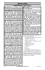
Page 18: ...of pressure will occur CAUTION For natural gas check your gas line pressure be fore connecting appliance to gas line Gas line pressure must be no greater than 10 5 WC for natural gas and 13 WC for propane If gas line pressure is higher appliance regulator damage could occur WARNING Donotover tighten gas connections CAUTION use pipe joint sealant that is resistant to gas Propane or Natural Gas For ...

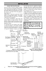
Page 19: ...he installer must supply an external regulator The external regulator will reduce incoming gas pressure You must reduce incoming gas pressure to between 11 and 13 of water If you do not reduce incoming gas pressure appliance regulator damage could occur Install external regula tor with the vent pointing down as shown in Figure 14 Pointing the vent down protects it from freezing rain or sleet Insta...

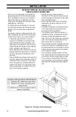
Page 20: ...sure They need to be of equal size unobstructed and spaced 180 apart The openings need to be a total area of 1 in lb 14 2 cm kg of fuel storage capacity Bottom opening must provide a minimum of 1 2 square inches for each pound of propane contained in the tank see example below Every opening must have a minimum dimensions to allow entrance of 1 8 diameter rod Ventilation openings in side walls must...

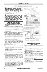
Page 21: ...S CONNECTIONS 1 Open equipment shutoff valve see Figure 17 2 Open main gas valve located on or near gas meter for natural gas or open propane supply tank valve 3 Make sure control knob of fireplace is in the OFF position 4 Check all joints from equipment shutoff valve to control valve see Figure 18 or 19 Apply a noncorrosive leak detection fluid to all joints Bubbles forming show a leak 5 Correct ...

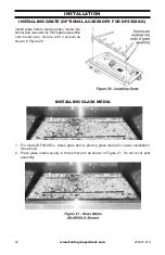
Page 22: ... glass media into burner pan see above Place grate assembly onto burner pan Secure with 2 screws as shown in Figure 20 INSTALLING GLASS MEDIA 1 For model DF450SS L install grate before placing glass media for easier installation See above 2 Place glass media evenly in the burner pan as shown in Figure 21 Do not cover pilot assembly ...

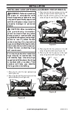
Page 23: ...logs will create soot It is very important to install the logs exactly as instructed Do not modify logs Use only logs suppliedwithfireplace Eachlog is marked with a number This number will help you identify the logs when installing 1 Place log 1 onto the rear grate prongs see Figure 22 2 Place logs 2 and 3 onto the front of the grate assembly see Figure 22 3 Place log 4 into the groves on the left...

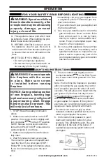
Page 24: ...ontrol knob cannot be turned from PILOT to OFF unless knob is pushed slightly Do not force 3 Make sure equipment shutoff valve is fully open 4 Wait 5 minutes to clear out any gas Then smell for gas around fireplace and near the floor If you smell gas STOP Follow B in the safety information above If you do not smell gas go to the next step WARNING You must operate this fireplace with the screen in ...

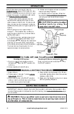
Page 25: ...llow the instructions To Turn Off Gas To Appliance and call your service technical or gas supplier Shutting Off Fireplace 1 Push in control knob slightly and turn clockwise to the OFF position Do not force 2 Close equipment shutoff valve Shutting Off Burner Only pilot stays lit Push in and turn knob clockwise to the PILOT position 1 Open Screen 2 Follow steps 1 through 7 under Lighting Instruction...

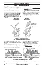
Page 26: ...es 29 through 32 Notice Do not mistake orange flames with yellow tipping Dirt or other fine particles enter the fireplace and burn causing brief patches of orange flame BURNER FLAME PATTERN For model DF450SS G the burner flames should rise approximately 3 to 6 above the burner For model DF450SS L Figure 28 shows a correct burner flame pattern Figure 29 shows an incorrect burner flame pattern actua...

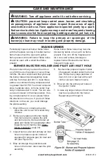
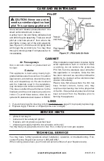
Page 27: ...We also recommend that you keep the burner tube and pilot assembly clean and free from dust and dirt To clean these parts we recommend using compressed air no greater than 30 PSI Your local computer store hardware store or home center may carry compressed air in a can You can use a vacuum cleaner in the blow position If us ing compressed air in a can please follow the directions on the can If you ...

Page 28: ...ed with stainless steel cleaner or WD40 When installation application includes highly acidic applications such or mortar or stone or etching do not remove the protective PVC film from the stainless steel until after this application is complete Once the film has been removed we recommend that the appliance be cleaned with a stainless steel cleaner immediately Please note that areas where the film ...

Page 29: ...the manufacturer TROUBLESHOOTING IMPORTANT Operating fireplace where impurities in air exist may create odors Clean ing supplies paint paint remover cigarette smoke cements and glues new carpet or textiles etc create fumes These fumes may mix with combustion air and create odors These odors will disappear over time Note All troubleshooting items are listed in order of operation Problem Possible Ca...

Page 30: ... propane gas supplier Pilotlightsbutflamegoes out when control knob is released 1 Control knob is not fully pressed in 2 Control knob is not pressed long enough 3 Equipment shutoff valve is not fully open 4 Thermocouple connection is loose at control valve 5 Pilot flame not touching thermocouple to cool caus ing pilot flame to go out This problem could be caused by the following A Low gas pressure...

Page 31: ... gas line 2 Air passageways on fire place are blocked 3 Dirty or partially clogged burner orifice 1 Operate burner until air is removed from line Have gas line checked by local gas supplier 2 Observe minimum installa tion clearances Figure 2 page 10 3 Clean burner see Care and Maintenance page 27 or replace burner orifice Fireplace produces a clicking ticking noise just after burner is list or shu...

Page 32: ...page 7 2 Correct log position or re place damaged logs see Inspecting Burners page 25 Installing Glass Media page 22 Installing Logs page 23 3 See Locating the Fireplace page 8 REPLACEMENT PARTS Note Use only original replacement parts This will protect your warranty coverage for parts replaced under warranty PARTS UNDER WARRANTY Contact authorized dealers of this product If they can t supply orig...

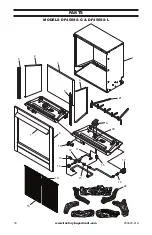
Page 33: ...www factorybuysdirect com 200423 01A 33 PARTS MODELS DF450SS G DF450SS L 1 2 5 3 4 6 8 7 9 20 10 11 12 13 21 14 18 22 13 15 16 17 19 ...

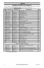
Page 34: ... 162479 02 Pilot Injector 1 12 161917 01 161917 01 Manual Control Valve 1 13 162206 01 162206 01 Fitting 5 8 18 UNF x 3 8 18 NPT 2 14 161933 01 161933 01 Manual Control Knob 1 15 NG 162546 01 NG 162546 01 Orifice and Retainer Assembly 1 LP 162547 01 LP 162547 01 Orifice and Retainer Assembly 16 161931 01 161931 01 Fitting 5 8 18 UNF x 9 16 24 UNEF 1 17 161915 1 161915 01 Regulator Single Fuel 1 18...

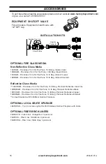
Page 35: ...r Fire Pans 10 lb Bag Classic Copper 14EMGM Fire Glass 1 4 in for Fire Pans 10 lb Bag Classic Emerald Reflective Glass Media 14RCRGM Fire Glass 1 4 in for Fire Pans 10 lb Bag Premium Reflective Clear Fire 14RBLKGM Fire Glass 1 4 in for Fire Pans 10 lb Bag Premium Reflective Black 14RCOGM Fire Glass 1 4 in for Fire Pans 10 lb Bag Premium Reflective Copper 14REMGM Fire Glass 1 4 in for Fire Pans 10 ...

Page 36: ...ith all local codes and instructions furnished with this product This warranty covers the cost of part s required to restore this product to proper operating condition and an allowance for labor when provided by a Factory Buys Direct Authorized Service Center or a provider ap proved by Factory Buys Direct Warranty parts must be obtained through authorized dealers of this product and or Factory Buy...

Reviews: