10
and one pin drops into hole. (Note: spacer nut should
not be rotated more than 221/2 before pin drops into
hole in gear.) It is preferable to tighten spacer nut
down instead of loosening.
25. Remove pin from aligned hole. Install half dog set
screw (68) and tighten half dog point into hole in
output gear (39). Remove remaining pin and proceed
with assembly. Note: One hole must be in alignment
to have proper assembly.
26. Lightly grease O.D. of translating tube (66) with
Duboise M.P.G. grease (no substitutes) and assemble
outer tube (55) assembly over translating tube (66)
and thread into housing (42) (a sealing compound
such as Non-Hardening Permatex 2 should be used
on threads).
27. Insert intermediate pinion shaft (32) in housing (42)
and place thrust washer (31) over shaft (32).
Assemble intermediate cluster gear (33) on shaft
and place thrust washer (31) on top.
28. Assemble bearing (28) on input pinion (29) (press on
inner bearing ring to prevent damage to bearing).
29. Pack housing (42) gear box cavity with Aeroshell #6
grease (no substitutes).
30. Assembly of Motor (53) to Housing (42)
a. Note location of flat on input pinion by marking
spot on the housing. See Figure 6-1B.
b. Insert grommet (50) on input pinion (29) between
coupling (47) posts and install “O”-Ring (52) in
cavity of insert (51).
c. Pack cavity with Aeroshell #6 grease.
d. If hole plug (54) is in rear end of motor, remove.
e. Feed motor (53) lead wires through hole in
housing (42) lining up couplings (47) on input
pinion (29) and motor (53) shaft. (Alignment is
critical at this point. See Figure 6-1B.)
NOTE
Input pinion (29) and motor (53) shaft flats are
opposite each other.
f. Assemble motor (53) into housing (42) . Before
assembling lock washers (46) and socket head
screws (45), hold motor firmly in place and,
with a screwdriver, turn motor shaft by using
screwdriver slot in end of motor shaft.
NOTE
Before turning motor shaft, make sure pinion shaft
has not been pushed out. It may be necessary to
hold pinion shaft down while turning motor shaft. If
couplings are properly installed, the motor can be
turned freely in both directions. If motor shaft will not
turn, this is an indication that couplings are not properly
aligned and assembly should be corrected.
g. Install lock washers (46) & socket head screws (45).
31. Insert dowel pins (27) in housing (42) and place
gasket (41) in place over dowel pins (27).
32. Install air vent (58) in outer tube (55) ( it may be
necessary to back outer tube out in order to install air
vent or to have vent in a more desireable position).
Spot drill tube and install set screw (33) to hold tube
in place.
33. Install spring (61) into end of screw (62).
NOTE
If unit has potentiometer assembly (26) and gear
(26b) does not have to be replaced or if unit has no
potentiometer feature, proceed to Step 35.
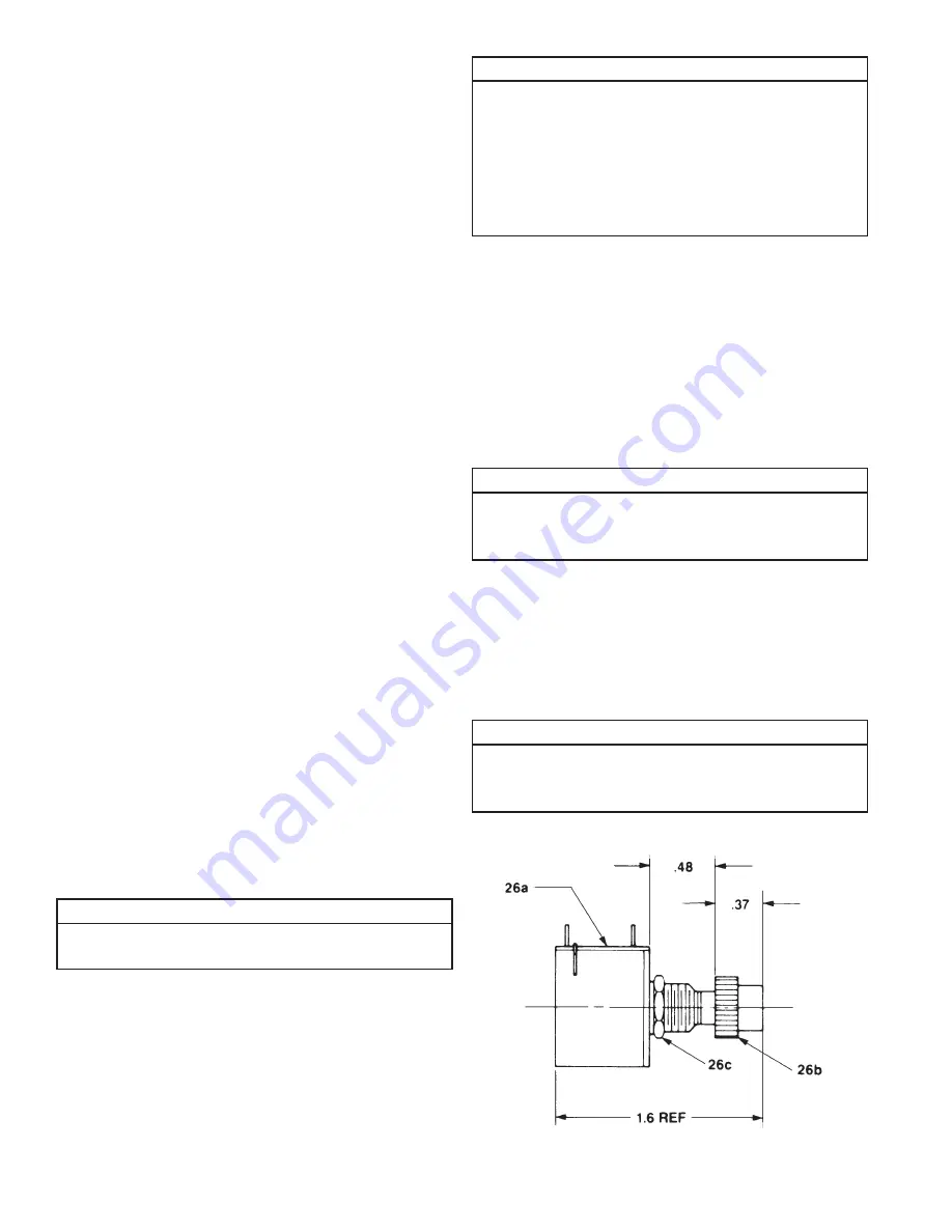
34. Potentiometer Assembly (26)
a. If nut and washer were removed from
potentiometer, assemble washer (26d) and nut
(26c) on potentiometer (26a). Nut (26c) should
not be tightened on potentiometer (26a) face.
b. Assemble gear (26b) on potentiometer (26a) shaft.
NOTE
Gear should be assembled with a very light press.
See sketch for required dimension of gear on
potentiometer. Take care not to damage potentiometer.
35.
Assembly of Cover (9)
Figure 4-1. Potentiometer Nut & Washer
Assembly
Summary of Contents for 6415 Series
Page 15: ...15 Notes...


