


Hardware/Software Interface
75
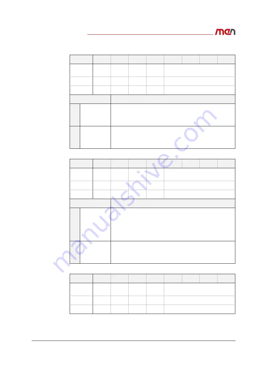
Table 36.
CPU module user LED and ignition watchdog data register (read) (offset
0x00
)
Table 37.
CPU module user LED and ignition watchdog data register (write) (offset
0x01
)
Table 38.
CPU module user LED and ignition watchdog configuration register (offset
0x03
)
Bit
7
6
5
4
3
2
1
0
Name
Reserved
WDOG
_EN
USR_LED4 USR_LED3
Reserved
Access
R
R
R
R
R
Reset
-
-
-
-
-
Bit Field
Description
6
WDOG_EN
Reset power supply watchdog (ignition)
0: Watchdog reset
1: Normal operation
5:4
USR_LED[4:3]
Turn user LED on or off
0: LED on
1: LED off (dimmed)
Bit
7
6
5
4
3
2
1
0
Name
Reserved
WDOG
_EN
USR_LED4 USR_LED3
Reserved
Access
W
W
W
W
W
Reset
1
1
1
1
1111
Bit Field
Description
6
WDOG_EN
Reset power supply watchdog (ignition)
0: Watchdog reset
1: Normal operation
Set the bit in sequence ’1’ > ’0’ to generate a falling edge to reset
the watchdog.
5:4
USR_LED[4:3]
Turn user LED on or off
0: LED on
1: LED off (dimmed)
Bit
7
6
5
4
3
2
1
0
Name
Reserved
WDOG
_EN
USR_LED4 USR_LED3
Reserved
Access
-
R/W
R/W
R/W
-
Reset
1
1
1
1
1111