


Getting Started
31
2.4.4
Connecting the Power Supply
Connect an external power supply:
»
Check the power configuration and coding labeling on the system for the exact config-
uration and pin assignment.
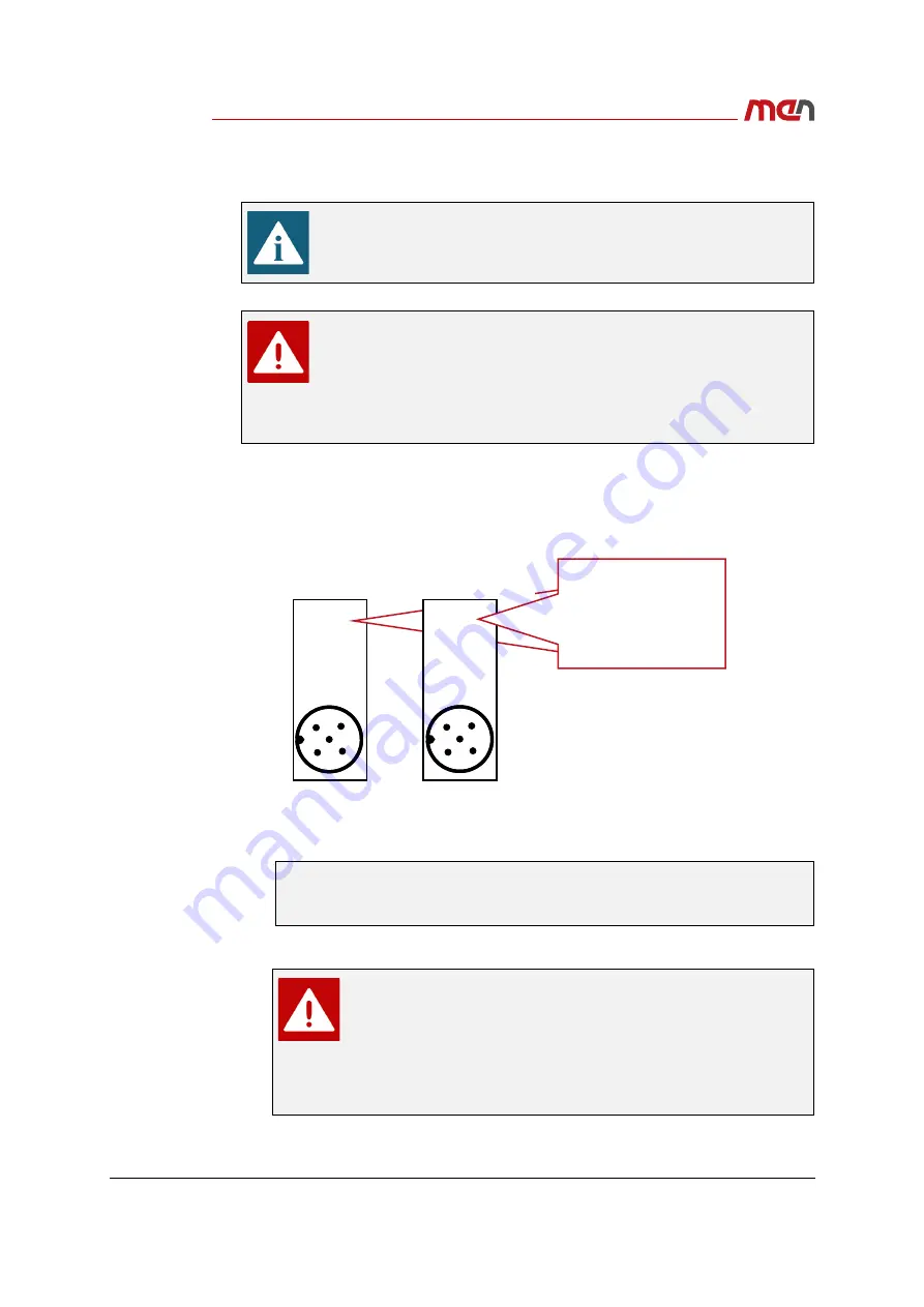
Figure 9.
Power configuration and coding labeling
»
Depending on your system configuration and product version choose the correct
power supply connector.
»
Plug an external power supply to the power inlet connector.
Make sure that an earthing cable has been connected to the system
before connecting an external power supply and switching on the system.
When using an MP1/MC50M combination, connect the power supply
and ignition input to the power inlet connector
PWR2
on the MP1.
When using an MP1/MC50M combination, do not remove the protective
cover on the MC50M.
Connecting the power supply to MC50M and MP1 simultaneously may
cause equipment damage or personal injury.
See
Chapter 2.4.4.1 Connecting the Power Supply to
an MP1/MC50M Combination on page 32
for further information on the power
supply connection.
To fulfill EN 62368-1, ensure that in the final installation the
external power supply does not provide more than 100 W. This can
be ensured by the power source itself or by using a suitable fuse.
When designing your circuit protection, consider the rated input
Figure 9, Power configuration and coding labeling on page 31
and the inrush current (see
Inrush current measurements on
).
1
3
2
4
5
Rated Input:
1: PWR
2: IGN
3: GND
4: GND
5: GND
For product versions
06MC50Mxx:
24VDC/1.7A
48VDC/0.85A
1
3
2
4
5
Rated Input:
24VDC/1.7A
48VDC/0.85A
1: PWR
2: NC
3: IGN_GND
4: GND
5: IGN
For prototype versions
06MC50MPxx:
Rated Input:
24VDC/1.7A
48VDC/0.85A