background image

S-21

In the factory default setting, all flight modes are inhibited. 

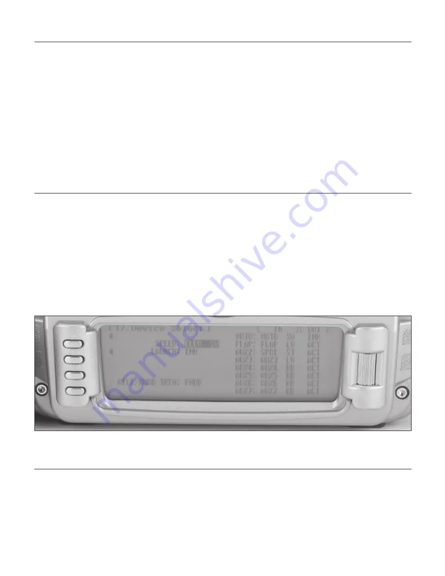
Flight modes are activated and assigned to the desired switch 

position using the SPEED and LAUN functions in the Device 

SEL screen.

In system mode list rotate the Selector until Device SEL is 

highlighted. Press the Selector to access the Device Select 

screen.

To activate the launch, cruise and land mode, rotate the Selector 

until LAUN is highlighted and then press the Selector. The 

following screen will appear: Device select w/ Launch screen.

At this point, you must decide which 3-position switch you 

prefer to assign the flight mode to. When a 3-position switch 

is selected, the launch, cruise and land will be activated. We 

recommend starting with the Flight Mode Switch (left top 

3 position switch), as this is a convenient place. Rotate the 

Selector until the desired switch is highlighted and press to 

select.

To activate the speed and thermal flight modes, highlight SPEED 

and press the Selector to select the desired switch position.

Important

: When the Speed and Thermal flight modes are 

activated, launches always have priority. Any time Launch 

is selected it will override Speed, Thermal or Cruise. To 

access Speed or Thermal, the Launch switch must be in 

the middle position. Try selecting the various flight modes 

several times while looking at the main info screen and 

you’ll quickly become familiar with the switch priority. 

Note

: On the main info screen, the flight mode that is 

activated will be displayed on the top center of the screen.

Activating and Assigning Primary Flight Modes

Activating and Assigning Additional Flight Modes

Aileron and Rudder Common Trims

The aileron and rudder trims can be programmed to operate 

independently in each flight mode (FMOD) or commonly, such 

that a rudder or aileron trim change will affect all flight modes 

(COM). Device select Aileron and rudder trim screen.

To select the aileron and rudder trims, highlight FMOD next to 

AILE/RUDD and press the Selector to select the desired trim 

position.

Summary of Contents for JR 12X

Page 1: ...I 1 INSTRUCTION AND PROGRAMMING MANUAL 12 CHANNEL COMPUTER RADIO SYSTEM WITH SPEKTRUM 2 4GHz DSM TECHNOLOGY...

Page 2: ...d I 17 ModelMatch I 18 Failsafe Functions I 18 SmartSafe I 19 Receiver Power Only I 19 After Connection I 19 Failsafe for JR Spektrum I 19 Receiver Power Only I 19 After Connection I 20 Programming Sm...

Page 3: ...e Name A 16 To Program a Flight Mode Name A 16 86 Transfer A 17 Preparing the 12X to Receive a Model Transfer A 17 Preparing the 12X to Send a Model Transfer A 18 97 Warning A 19 To Program a Warning...

Page 4: ...Program the Balance Function A 38 44 Gyro Sensor A 39 Gyro Connections A 39 Gyro Gain A 39 To Access the Gyro Sensor A 39 45 Governer A 40 To Activate the Governor Screen A 40 To Access the Governor S...

Page 5: ...raph A 56 Points That Can Be Added and Adjusted A 56 Exponential A 56 Pitch Channel Position A 56 Throttle Channel Position A 56 Switch Select A 57 CLR Button A 57 LIST Button A 57 ENT Button A 57 75...

Page 6: ...vice Select H 20 Assigning the Flight Mode Switch H 20 To Assign the Flight Mode to a Switch H 20 Activating Extra Flight Modes 3 and 4 H 21 To Activate 2 Additional Flight Modes Flight Modes 3 and 4...

Page 7: ...Accessing the Tail Curve Function H 38 Exponential H 38 61 Dual Pitch H 39 65 Swashplate Mix H 40 Aileron Elevator and Pitch Authority H 40 Aileron to Elevator Elevator to Aileron Mix H 40 3D Electron...

Page 8: ...Accessing the System Menu S 5 84 Model Select Copy Function S 6 To Select a Model Memory S 6 Model Copy S 7 To Copy a Model to Another Internal Memory S 7 81 Model Name S 8 To Name a Model S 8 28 Mod...

Page 9: ...26 To Program Sub Trim Values S 26 Motor Hold S 26 To Access Motor Hold in the Function List S 26 21 Flaperon Mix S 27 To Access Flaperon Mix S 27 24 Servo Speed S 28 To Adjust Servo Speed S 28 25 Cam...

Page 10: ...43 LIST Button S 43 ENT Button S 43 To Inhibit a Mixer Turn it off completely S 43 75 Monitor S 44 76 Mix Monitor S 44 78 Trainer S 45 12X Used as Master Instructor S 45 12X Used as Slave Student S 45...

Page 11: ...information e g charging batteries binding range checking and Frequently Asked Questions sections that are common to all model types The remaining three sections pages A 1 through S 41 include instru...

Page 12: ...ramming should the main transmitter battery ever fail or need replacing When the transmitter voltage drops below 9 0 volts the display flashes BATT LOW and an alarm sounds If you are flying when this...

Page 13: ...H 1 48 x 2 1 x 628 in Weight Main 7 oz 20 g Remote 3 g 2 oz each Current 70mA Voltage Range 3 5 to 10V Resolution 2048 Note The 12X includes a JR1221 12 channel receiver The 12X is also compatible wil...

Page 14: ...center pin on all JR transmitters is negative Therefore the center pin on all JR chargers is negative not positive This is different from many other manufacturers chargers and radio systems Beware of...

Page 15: ...left down allowing the pilot to be aware of the general trim position audibly without looking at the transmitter By using the Trim System Function Code 83 located in the System Mode the amount of trav...

Page 16: ...nal Using double sided foam tape servo tape mount the remote receiver s keeping the remote antenna s at least 2 away from the primary antenna Ideally the antennas will be oriented perpendicular to eac...

Page 17: ...he bind mode RE M O VE BE FO RE U SE 2 Turn on the receiver switch Note that the LED s on all receivers should be flashing indicating that the receiver is ready to bind Binding 3 Establish the desired...

Page 18: ...memory 1 through 50 that the transmitter is currently programmed to Later if the incorrect model memory in the transmitter is selected and the receiver is turned on the model simply won t operate pre...

Page 19: ...rtSafe drives the throttle servo only to its preset fail safe position low throttle that was set during binding All other channels hold their last position When the signal is regained the system immed...

Page 20: ...control sticks and switches in the desired fail safe positions bind the transmitter to the receiver by pressing and holding the bind buttons on the back of the transmitter module and turning on the tr...

Page 21: ...the model with the button depressed at 30 paces 90 feet 4 If control issues exist call the Product Support Department at 1 877 504 0233 for further assistance Advanced Range Testing Using a Flight Lo...

Page 22: ...here For giant scale aircraft it s recommended that the airplane be tipped up on its nose and rotated 360 degrees for one minute then record the data Next place the airplane on its wheels and do a se...

Page 23: ...kes about one second If a hold occurs during a flight it s important to re evaluate the system moving the antennas to different locations and or checking to be sure the transmitter and receivers are a...

Page 24: ...for a single heavy duty servo battery lead is three amps while short duration current spikes of up to five amps are acceptable Consequently if your system draws more than three amps continuous or five...

Page 25: ...ed in should a loss of signal occur failsafe the system connects immediately 4ms when the signal is regained Q I ve heard that the DSM system is less tolerant of low voltage Is that correct A All DSM...

Page 26: ...ight Many of our customers have experienced failures using 3 cell Li Po packs and their use in JR and Spektrum transmitters is highly advised against The 12X system will operate for over 8 hours using...

Page 27: ...0 Trim Steps L S T trim trim can be programmed to affect endpoints or center point only Elevator To Flap mixing Airplane ACRO Mode Aileron To Flap mixing Governor mixing Balance mixing allows precise...

Page 28: ...Switch AUX 5 Knob Throttle Trim Aileron Elevator Stick Mix Switch Handle Flap Switch Throttle Rudder Stick Rudder D R Switch Elevator Trim Rolling selector Flight Mode Switch LCD Screen AUX 4 Knob Ru...

Page 29: ...utton AUX 7 Knob Handle Left Slider Aileron Spring Tension Cover AUX 6 Knob Trainer Transfer PC Interface Jack Right Slider Elevator Spring Tension Cover Rudder D R Charge Jack Throttle Spring Tension...

Page 30: ...should appear as shown above SYSTEM MODE LIST System mode contains the follow screens 84 Model SEL Model Select Page A 6 81 MDL Name Model Name Page A 8 28 MDL Reset Model Reset Page A 9 89 Type SEL...

Page 31: ...oll Page A 36 32 DIFFEREN Differential Page A 37 33 Balance Balance Page A 38 44 Gyro SENS Gyro Sensor Page A 39 45 Governor Governor Page A 40 62 AILE RUDD Aileron to Rudder Mix Page A 41 63 ELEV FLA...

Page 32: ...ent models to be stored and selected in up to 50 individual model memories This screen also allows a model to be copied from the current selected model to any of the other 49 available internal model...

Page 33: ...2 Use the rolling Selector to highlight Select then press the roller to access Model Copy 3 Rotate the roller to select the desired model memory that you wish to copy the current program to 1 50 4 Pre...

Page 34: ...oller indicates where the next character will be placed at the beginning of the model name Press the Selector to obtain a list of available characters 3 Highlight and select the desired character to f...

Page 35: ...is to ensure that there are no programming values or functions active from a previous model or programming session 28 Model Reset 1 In the SYSTEM MODE highlight and select MDL Reset using the Selecto...

Page 36: ...programming information will be reset to the factory default setting losing the previous settings 89 Type Select 1 In the SYSTEM MODE highlight and select Type SEL using the Selector 2 Highlight and s...

Page 37: ...riate to the module selected The Modulation screen code 85 allows the selection of modulation for 72MHz receiver types Modulation types available are Note APCM JR s newest version PCM not available in...

Page 38: ...MHz or 2 4GHz Note that the transmitter automatically detects which module is installed and modifies the accessible programming appropriate to the module selected The Frequency Select function allows...

Page 39: ...movements When adjusting the analog throttle trim however the total trim travel is actually reduced when set to less than 100 Use a fairly coarse setting such as the factory default 4 when test flying...

Page 40: ...the L S T Trim Function Note The Flap and AUX trims are adjustable from 0 to 200 and can be turned off or on by selecting On or Off Moment in the trim function is used to make the Flap Trimmer and Aux...

Page 41: ...on Elevator and Rudder 4 Rotate the roller to select POS and adjust to the desired value that you wish to have the mix function turn off on 0 center L100 Left full stick travel etc Note ON OFF is disp...

Page 42: ...access the list of the available characters 3 Highlight and select the desired character to form the flight mode name After the character is selected rotate the Selector to position the cursor where...

Page 43: ...FER in the SYSTEM Menu to obtain the Transfer display 3 If RECEIVE is already displayed continue with the next step If TRANSMIT is displayed highlight and select TRANSMIT changing it to RECEIVE 4 Sele...

Page 44: ...86 in the SYSTEM Menu to obtain the Transfer display 2 The model to be transferred must be the currently selected model If the model to be transferred is not currently selected see Model SEL in the S...

Page 45: ...osition Switch 0 Stick Position Switch 1 Stick Position Switch 2 Stick Position Switch 3 Throttle Stick Position Aileron 1 Aileron 2 AUX2 up AUX2 middle AUX2 down 97 Warning 1 In the SYSTEM MODE highl...

Page 46: ...ese functions are defaulted to Backlight Auto and Silent Mode off 98 Settings 1 In the SYSTEM MODE highlight and select Settings using the Selector 2 Highlight the desired function Display backlight o...

Page 47: ...nt aircraft settings for Take Off Flying and Landing for a turbine powered jet aircraft Flight Modes can make the pilot s job easier by configuring and optimizing the aircraft to do different things b...

Page 48: ...W Aileron D R SW or INH Highlight and select the desired flight mode switch Once Flight Modes have been activated FLAP TRIM and TRIM appears on the display 3 To activate the two extra flight modes usi...

Page 49: ...tch position and direction is assigned in Device Select The actual programming of the throttle hold position is done in Code 16 Throttle Hold screen in the Function mode see page A 33 1 In Device Sele...

Page 50: ...ion by using the Selector to highlight either ON or OFF and pressing the Selector The flap trim is defaulted to ON Flap Trim Ordinarily this switch should be turned OFF even if the aircraft has flaps...

Page 51: ...ery useful feature if switching between Flight Modes causes the aircraft s trim to change such as when flaps are deployed by one of the Flight Modes causing the aircraft to have a pitch change In this...

Page 52: ...ified above are to be used as a 2nd channel for a primary flight control AILE ELEV RUDD FLAP then be sure to Inhibit INH the switches for the channels in this function or they will not be available to...

Page 53: ...a V Tail configuration where the 2 tail control surfaces are used for both Elevator and Rudder control Wing Type allows Dual Aileron Dual Elevator Dual Rudder and Dual Flap functions to be activated T...

Page 54: ...h6 of the receiver Wing Type To Program a Wing Type Note If the ailerons are not going to actually be used as flaps inhibit the FLAP Switch and FLAP TRIM in the Devic SEL function in the SYSTEM Menu T...

Page 55: ...is to be the Mate slave to the control channel represented above it Plug the 2nd control surface servo into the channel selected as the Mate 3 INH will appear on the Trim Line of the display directly...

Page 56: ...twin engines the Twin Engine feature Twin E may be used for a 2nd throttle channel with an optional separate digital trim 1 Highlight and select INH next to Mate under Twin ENGIN A list of available c...

Page 57: ...e Selector The direction of travel is changed by moving the stick switch lever in the desired direction to highlight L R U D or To Program Travel Adjust Values The servo reverse screen allows the dire...

Page 58: ...he auto function 3 Highlight and select the desired channel Aileron Elevator or Rudder noting that 3 sets of values will be displayed if three flight modes are active and 5 sets of values will be disp...

Page 59: ...Highlight IHN and press the roller to activate the Throttle Hold function To Activate Throttle Hold switch position and direction is assigned in Device Select The programming of the throttle hold swit...

Page 60: ...es providing a total of 4 possible throttle curves However instead of being named Pos0 Pos1 they are named RTH 0 RTH 1 LTH 0 and LTH 1 They represent Right Throttle Pos0 Pos1 and Left Throttle Pos0 Po...

Page 61: ...itions in this screen should be P0 If two servo speeds are desired then assign the desired switch that will change the servo speed to P1 Return to the main screen 3 If a single set of servo speeds is...

Page 62: ...when the stick is displaced beyond the programmed position Important Use this function with extreme caution If Flight Modes have been activated up to 5 Snap Roll directions rates can be assigned one...

Page 63: ...the Aileron Differential display 2 If there is to be a single Aileron differential setting that is on all of the time highlight and select Pos0 and adjust the desired percentage of differential A posi...

Page 64: ...n is selected in the Wing Type or if any of the dual functions e g dual elevator dual rudder etc is activated in Wing Type 33 Balance 1 Highlight and select Balance in the FUNC LIST to obtain the Bala...

Page 65: ...AILE D R ELEV D R FLAP SW AUX or AUTO for flight mode 3 Two types of gyro adjustments are provided Normal and Tail Lock Highlight and select the desired type of gyro that will be used If heading lock...

Page 66: ...access the governor screen 45 Governer 1 In the Devic SEL function use the Selector to highlight under OUT the GEAR Aux 2 or Aux 3 channel GEAR Aux 2 or Aux 3 must be programmed to GOV in order to ac...

Page 67: ...ve value will reverse the direction 3 Highlight and select R next to Pos1 and set the value to give the desired amount of Right Rudder A negative value will reverse the direction 62 Aileron to Rudder...

Page 68: ...e mixer may be turned on and off Pos0 will be OFF and Pos1 will be ON this can be reversed by leaving the Pos1 values at zero and putting values in Pos0 Highlight and select DN next to Pos1 and set th...

Page 69: ...der to Aileron Elevator display 2 Scroll to the desired value aileron or elevator right or left position 0 or 1 and press the roller to select that value Rotate the roller to program the desired mix v...

Page 70: ...ised above a specified throttle position This can be useful during a missed landing approach when a go around is required The Flap System allows the Flaps to be deployed using the Flap Switch Flight M...

Page 71: ...up to a maximum of 2 seconds 1 Highlight and select Delay in the Flap System display using the Selector Then use the rotary to select a delay between 1 second and 2 seconds Delay Flap ELEV Elevator C...

Page 72: ...ixes can always be on or turned off and on via a programmed switch Stick position or flight mode The Snap Roll Trainer switch momentary switch SNPT can also be programmed as the Master channel If dual...

Page 73: ...or to indicate that these channels can also be used as a Master while bypassing any Dual Rate and Exponential settings that may be associated with them They are designated by pound sign in front of th...

Page 74: ...ntains each of the 12 channels in the system and CANCEL The right side of the Programmable mix screen displays the available switch options If you choose to have a switch control the mix either on off...

Page 75: ...os1 Each set can have 2 percentages which control movement of the slave when the master is moved in each direction A switch can be selected to switch between the Pos0 and Pos1 percentages The Pos0 set...

Page 76: ...s that appear more than once They are Throttle Aileron Elevator and Rudder Since these channels can be influenced by Dual Rate Exponential and Throttle Curve settings they are included in the list twi...

Page 77: ...om 100 to 100 A value of 0 indicates the Slave s center or neutral position The overall travel of the slave channel is affected by the Travel settings described in the TRVL ADJ function The value for...

Page 78: ...ion Exponential The Exponential function blends the Curve between the points on the graph to provide a smooth response The default value is OFF To turn it on and smooth the mixing curve highlight and...

Page 79: ...meter to its default value Note Pressing the CLR button when either the Master or Slave is highlighted inhibits the entire mix Switch Select CLR Button LIST Button Press the LIST button to return to t...

Page 80: ...ed in the Wing Type function To access Aileron to Flap mix in FUNC LIST rotate the Selector until AIL FLP M is highlighted Press the Selector to access the Aileron to Flap mix Note Two Aileron to Flap...

Page 81: ...AUX2 or the AUX 3 channel to allow access to the Pitch Curve Function The points that can be adjusted are listed vertically by name Point L 1 2 H etc and are also displayed by number on the graph Chan...

Page 82: ...is OFF To turn it on and smooth the mixing curve highlight and select OFF and it will toggle to ON The Pitch servo position next to OUT at the bottom left of the display is expressed in values from 0...

Page 83: ...lect a switch that will switch between the Pos0 and Pos1 values highlight and select the switch name and it will toggle between Pos0 and Pos1 CLR Button Pressing the CLR button while a modifiable para...

Page 84: ...and shows the movement of channels when sticks levers and switches are moved It renames channels according to special assignments to assist in identifying each channel For instance when Flaperon is t...

Page 85: ...Connect DSC POWER off Make sure the Tx power switch is in the OFF position and the Trainer cord is connected between the 2 transmitters The 12X is now ready to be used as the Slave or student Tx 78 T...

Page 86: ...IMER2 and then select DOWN T of STOP W Use the Selector to set the countdown set time interval down alarm and one time functions Once the timer is set TIM will appear on the Main display in the lower...

Page 87: ...140 3 servo 90 4 servo 90 Electronic 3D Cyclic Ring prevents overdriving the cyclic servos with combined aileron and elevator commands Adjustable Trim Rates 10 100 trim steps Aileron to elevator and...

Page 88: ...as the functions appear in the transmitter beginning with the System Menu functions and then the Function Menu functions Flight Mode Switch Antenna Elevator D R Switch Power Switch AUX 5 Knob Throttl...

Page 89: ...y Door AUX 7 Knob Handle Left Lever Aileron Spring Tension Cover AUX 6 Knob Trainer transfer PC Interface Jack Right Lever Elevator Spring Tension Cover Rudder D R Charge Jack Throttle Spring Tension...

Page 90: ...creen should appear as follows System Mode To Enter System Mode System Mode List System mode contains the follow screens 84 Model SEL Model Select Page H 6 81 MDL Name Model Name Page H 8 28 MDL Reset...

Page 91: ...am Mix 2 Page H 44 53 PROG MIX3 Program Mix 3 Page H 44 54 PROG MIX4 Program Mix 4 Page H 44 55 PROG MIX5 Program Mix 5 Page H 44 56 PROG MIX6 Program Mix 6 Page H 44 57 PROG MIX7 Program Mix 7 Page H...

Page 92: ...Use the rolling Selector to highlight MODEL then press the roller and select the desired model number to be used using the rolling selector 3 Return to the System Menu by pressing the LIST button Mode...

Page 93: ...e roller to access model select 3 Rotate the roller to select the desired model memory that you wish to copy the current program to 1 50 4 Press the roller to select the highlighted model that you wis...

Page 94: ...el to be given up to a sixteen digit name or number This is convenient for identifying a model The model s name will appear on the main info screen 81 Model Name To Name a Model 28 Model Reset Model R...

Page 95: ...rogramming information will be reset to the factory default setting losing the previous settings 1 In the System Menu highlight and select Type SEL using the Selector 2 Highlight and select HELI using...

Page 96: ...gramming appropriate to the module selected The Modulation screen code 85 allows the selection of modulation for 72MHz receiver types Modulation types available are APCM JR s newest version PCM SPCM M...

Page 97: ...and the system is turned on the antenna must be attached Operating the 72MHz module without the antenna attached could overload the internal transistor causing a failure Warning Only the JR TSM 72A a...

Page 98: ...tion as a Momentary switch by selecting ON under Moment for either or both trimmers When adjusting the digital trims AILE ELEV RUDD the total trim travel does not change only the number of increments...

Page 99: ...im Rates To Select the L S T Trim Function Note The Hover Throttle and Hover Pitch trims are adjustable from 0 to 200 and can be turned off or on by selecting On or Off Moment in the trim function is...

Page 100: ...ave the mix function turn off on 0 center L100 left full stick travel etc Note ON OFF is displayed at the top of the screen and when moving the stick this will indicate that the function is working 5...

Page 101: ...access the list of the available characters 3 Highlight and select the desired character to form the flight mode name After the character is selected rotate the Selector to position the cursor where t...

Page 102: ...Highlight and select TRANSFER in the SYSTEM Menu to obtain the Transfer display 3 If RECEIVE is already displayed continue with the next step If TRANSMIT is displayed highlight and select TRANSMIT cha...

Page 103: ...er display 3 The model to be transferred must be the currently selected model If the model to be transferred is not currently selected see Model SEL in the SYSTEM Menu to select the model to be transf...

Page 104: ...AX22 RUD1 RUD2 Stick Position Switch 0 Stick Position Switch 1 Stick Position Switch 2 Stick Position Switch 3 Throttle Stick Position 97 Warning To Program a Warning 1 In the SYSTEM Menu highlight a...

Page 105: ...se functions are defaulted to Backlight Auto and Silent Mode off 1 In the SYSTEM MODE highlight and select Settings using the Selector 2 Highlight the desired function Display Back Light or Silent Mod...

Page 106: ...yro function Activate inhibit the Pit2 dual pitch servo function Assign functions and channel to the desired switch knob or lever Each of these options is described below 17 Device Select Assigning th...

Page 107: ...D R ELE D R RUD D R HOLD SW and GEAR SW Highlight and select the switch that is to be used to access Extra Flight Modes Once Extra Flight Modes have been activated two additional sets of Throttle and...

Page 108: ...all stunt modes COM or to allow each flight mode to have its own individual trims FMOD The STUNT TRIM COM parameter can be toggled back and forth between COM and FMOD by pressing the Rolling Selector...

Page 109: ...If ACT is selected the AUX 4 and AUX 5 knobs are programmed for hovering throttle and hovering pitch If INH is selected the right and left digital trimmers are programmed for hovering throttle and hov...

Page 110: ...ce select program provides the ability to activate and assign the Governor Gyro and Pitch 2 functions to one of the following channels GEAR AUX2 AUX3 Note The Governor and Pitch 2 functions are defaul...

Page 111: ...lowing them to be used as slave channels Also the deactivated channels will assume a centered 1 50ms position needed for mixing 1 IF GEAR AUX2 thru AUX7 are to be used as slave channels then inhibit t...

Page 112: ...hanical mixing type 2 Servo 180 3 Servo 120 CCPM most popular 3 Servo 140 CCPM JR Vibe 90 50 3 Servo 90 CCPM 4 Servo 90 CCPM 34 Swashplate Type To Select a Swashplate Type 1 In the SYSTEM Menu highlig...

Page 113: ...ected Function Mode To Enter the Function Mode List 11 Servo Reversing To Program Servo Reverse 1 Highlight and select REV SW in the FUNC LIST to obtain the servo reversing display and Throttle Curves...

Page 114: ...the FUNC LIST to obtain the Travel Adjust display 2 Use the Selector to highlight and select each channel and adjust the travel in each direction by rotating the Selector The direction of travel is c...

Page 115: ...operate in each flight mode AUTO Note that D R and Expo values can be independently adjusted by holding the corresponding control stick in the desired direction while making adjustments Note VTR or V...

Page 116: ...ctive flight modes will be displayed Select SW D R switch or Pos1 through 5 and that position will be active when the corresponding flight mode is selected Use Sub Trims to fine tune the output alignm...

Page 117: ...ugh To Activate the Stick Auto Function 1 Highlight the Stick Auto function with the selector and press to access Next roll the selector to increase decrease the position of the cutoff point Hold Dela...

Page 118: ...e trimmer and throttle trim has no effect on the input values of the throttle curve Each of the eight points of the throttle curve is independently adjustable from 0 100 1 In function mode use the Rol...

Page 119: ...ivity of the throttle trimmer To adjust the throttle trim authority highlight TRIM and adjust the value using the roller Note the onscreen graph can be used to indicate the trim value changes Note The...

Page 120: ...e adjusted Once a direction for a servo is selected the servo speed may be set so the servo travels from 193 seconds for 60 degrees of rotation to 16 4 seconds for 60 degrees of rotation Adjust the sp...

Page 121: ...2 Highlight the desired value to be adjusted with the Rolling Selector and then press to open the options box Roll the Rolling Selector to adjust the value as needed Selecting the Desired Flight Mode...

Page 122: ...de to access the Gyro Sensor function 2 To select the switch or function that will be used select gyro gain settings Highlight Manual then press the Rolling Selector to select the desired switch auto...

Page 123: ...rnor programs operational channel can be assigned to the Gear Aux1 or Aux2 channels in the Device Select screen Note To access the Governor function the Gear Aux1 or Aux 2 channels must be programmed...

Page 124: ...ft corner of the screen 3 Move the Rolling Selector and highlight the desired point to be adjusted Press the Rolling Selector to access the point value then roll the Rolling Selector to increase and d...

Page 125: ...output positions to be accurately matched at 7 points throughout the stroke Note This function is only available if the 1 servo NORM is selected in swashplate type and if the PIT function is assigned...

Page 126: ...125 defaulted to 60 This mix is used to correct for swashplate interactions i e elevator input resulting in slight roll output By mixing elevator to opposite aileron this interaction can be corrected...

Page 127: ...n elevator and elevator aileron mix then highlight SW SEL A screen will appear that will allow several switches and flight modes to be selected to turn on off the mix function This function compensate...

Page 128: ...ight points of the throttle curve are independently adjustable from 0 100 8 In function mode use the Rolling Selector to highlight the PIT CURV function then press to access ALL SERVOS HOLD will be di...

Page 129: ...hlight and select OFF and it will toggle to ON Hovering Pitch Hovering Pitch increases or decreases the servo output via the trimmer or knob for the selected points set for the pitch curve Use of the...

Page 130: ...l channels to be operated via a trimmer or lever Additionally programmable mixes can always be on or turned off and on via a programmed switch Stick position or flight mode The Snap Roll Trainer switc...

Page 131: ...ted there is a special designator to indicate that these channels can also be used as a master while bypassing any Dual Rate and Exponential settings that may be associated with them They are designat...

Page 132: ...contains each of the 12 channels in the system and CANCEL The right side of the Programmable mix screen displays the available switch options If you choose to have a switch control the mix either on o...

Page 133: ...values Pos0 and Pos1 Each set can have 2 percentages which control movement of the slave when the master is moved in each direction A switch can be selected to switch between the Pos0 and Pos1 percen...

Page 134: ...ly disable a mixer CLR Button Std Prog Mixer Multi Point Programmable Mixer There are 4 Multi Point Programmable Mixers in the 12x Prog Mix4 thru Prog Mix8 They differ from the standard mixes in that...

Page 135: ...s a trim include function By selecting a channel with the the trim lever affects both the master and slave channels This is the slave channel that will move according to the program mix in relation to...

Page 136: ...e direction from neutral and the top portion of the graph is the other direction Curve mixes are defaulted to three points L 1 and H Up to five additional point can be added To add a point move the ma...

Page 137: ...ic SEL function then flight mode switches may be selected Also Switch positions can be used to selected between Pos0 and Pos1 To select a switch that will switch between the Pos0 and Pos1 values highl...

Page 138: ...ay to determine which functions are activated 1 To access the Mix Monitor screen highlight and select MIX MON in the FUNC LIST to obtain the Mix Monitor display 75 Monitor 76 Mix Monitor Flaperon is t...

Page 139: ...ll channel selectors are in the MAST position NORMAL appears on the display and all 4 channels are transferred to the student when the trainer switch is depressed 12X Used as Master Instructor If only...

Page 140: ...ctor to confirm the selection The desired set time beep interval down alarm can be set as desired When the One Time function is ON the timer will start with the switch selected but pressing the switch...

Page 141: ...ogramming V tail mixing Stick Position switches allow mixing functions to be turned on off via a stick position Fully programmable motor function Camber programming for each flight mode Warning system...

Page 142: ...Throttle Trim Aileron Elevator Stick Mix Switch Handle Flap Mix Switch Throttle Rudder Stick Rudder D R Switch Elevator Trim Rolling Selector Gear Switch LCD Screen AUX 4 Knob Rudder Trim Left Side Le...

Page 143: ...Left Lever Aileron Spring Tension Cover AUX 6 Knob Trainer Transfer PC Interface Jack Right Lever Elevator Spring Tension Cover Rudder D R Charge Jack Throttle Spring Tension Cover Rudder Spring Tens...

Page 144: ...ng type etc functions that are typically set once during setup and then are seldom changed or adjusted Below and throughout this section the functions are in the order that they appear in the System M...

Page 145: ...ge S 30 44 Gyro SENS Gyro Sensor Page S 31 46 RUDD SPOI Rudder to Spoiler Mix Page S 31 62 AILE RUDD Aileron to Rudder Mix Page S 32 Function Mode To Enter Function Mode 63 ELEV FLAP Elevator to Flap...

Page 146: ...n setting up a new model it is recommended that an unused model memory is selected If a current model memory is selected it s recommended that the model be reset to factory default settings before pro...

Page 147: ...eturn to the SYSTEM Menu by pressing the LIST button Note The model memory that is copied to will be replaced with the current model memory programming It is recommended that a model memory that is no...

Page 148: ...e the next character will be placed is positioned at the beginning of the model name Press the Selector to obtain a list of available characters 3 Highlight and select the desired character to form th...

Page 149: ...their default or factory settings before 1 In the SYSTEM MODE highlight and select MDL Reset using the Selector 2 Press the CLR button that is next to RES on the display 28 Model Reset 89 Type Select...

Page 150: ...g a failure Warning Only the JR TSM 72A and JRM2 4 modules are compatible with the 12X MV Do not install a standard type JR Spektrum or other branded module in the 12X as damage will occur The 12X MV...

Page 151: ...system is turned on the antenna must be attached Operating the 72MHz module without the antenna attached could overload the internal transistor causing a failure Warning Only the JR TSM 72A and JRM2...

Page 152: ...adjusts the servo output by 10 s and there are only 10 trim increments from center to each end When set to 5 the output is changed 5 s per trim step and there are 20 trim increments from center to ea...

Page 153: ...ct L S T or NORM 2 Repeat for other channels as desired Note The Flap and Flaperon trims are adjustable from 0 to 200 and can be turned off or on by selecting On or Off Moment in the trim function is...

Page 154: ...a value in the POS then highlight the SYM and activate it using the roller The center can now be programmed to turn on or off by selecting the ON and highlighting Low High or Right Left Note The abov...

Page 155: ...desired flight mode character position using the roller then press the roller to access the list of the available characters 3 Highlight and select the desired character to form the flight mode name A...

Page 156: ...el name memory number can not be the currently selected model If you wish to receive a model in the currently selected model name memory number go to the model select function and select a different m...

Page 157: ...86 in the SYSTEM Menu to obtain the Transfer display 2 The model to be transferred must be the currently selected model If the model to be transferred is not currently selected see Model SEL in the S...

Page 158: ...ON select Low or Hi to have the alarm sound above or below the POS position 5 Return to the SYSTEM Menu by pressing the LIST button The Warning function can be programmed to sound an alarm if a selec...

Page 159: ...desired function Display back light or Silent Mode using the roller then press the roller to access and change the settings 3 Return to the SYSTEM Menu by pressing the LIST button Device Select is us...

Page 160: ...eron differential is now at a much higher 75 for more coordinated thermal turns At the flip of a single switch you re ready for a zoom launch and for hunting thermals And remember there are 3 more fli...

Page 161: ...nd thermal flight modes highlight SPEED and press the Selector to select the desired switch position Important When the Speed and Thermal flight modes are activated launches always have priority Any t...

Page 162: ...ns The Flap and Auxiliary channels can be assigned to operate from several different switches buttons or the throttle stick In Device Select highlight the desired Flap or Aux function and press the Se...

Page 163: ...Trim Servo Speed Flaperon mixes Camber system Differential Programmable Mixes Gyro programming brake system Trainer and Timer functions etc Many of these functions are frequently used to adjust the fl...

Page 164: ...Travel Adjust allows the independent adjustment of servo travel for each direction of servo travel 11 Servo Reversing To Program Servo Reverse 12 Travel Adjust To program Travel Adjust Values 1 Highl...

Page 165: ...be independently adjusted by holding the corresponding control stick in the desired direction while making adjustments 4 To Select a Curve Type highlight CURVE TYPE POS 1 thru 5 will appear on the scr...

Page 166: ...an electric motor and switching to another mode Landing the spoiler stick can be used as landing flaps When the Motor Hold mix is on the Throttle Hold program holds the throttle in the desired positi...

Page 167: ...he Selector to access the Flaperon Mix menu 2 Highlight Flap LV Offset and program the desired Flap lever offset This value establishes the center point at which the up down or left right mix occurs 0...

Page 168: ...peed may be set so the servo travels from 193 seconds for 60 degrees of rotation to 16 4 seconds for 60 degrees of rotation Adjust the speed of each servo until the desired speed is obtained 4 If 2 se...

Page 169: ...o one of many different levers or switches in the Device Select screen The default is the left lever Mix values are based on a percentage of the flap values so until a flap value is programmed in code...

Page 170: ...e Highlight the AILE or Brake DIFF to program the desired values A positive differential value causes the downward Aileron to travel less The Aileron Differential function provides for up to 5 Differe...

Page 171: ...columns will appear in the balance screen This also applies to the dual elevator and rudder functions linkage geometry inaccuracies The Balance function allows the servo output of the master servo to...

Page 172: ...acteristics especially on landings Rudder to Spoiler mix values can be independently adjusted for each of the 5 flight modes 46 Rudder to Spoiler Mix To Access Rudder to Spoiler Mix 1 In FUNC LIST rot...

Page 173: ...Press the Selector to access the Aileron to Rudder mix menu 5 Rotate the Selector to highlight the desired value corresponding to the flight mode and desired direction and then press the Selector to...

Page 174: ...Mix To Access Elevator to Flap Mix 1 In Function Mode list rotate the Selector until ELE FLP M is highlighted Press the Selector to access the Elevator to Flap mix menu 2 Note that Elevator to Flap m...

Page 175: ...ed in conjunction with the Flaperon Mix function Code 21 to adjust the desired camber setting ranges when using the flap levers for each flight mode To Access the Flap Rate Function 1 In Function Mode...

Page 176: ...utral position trailing edge level occurs when the spoiler stick is in the full up position If you choose to locate the neutral position in the down position the value would be 100 2 Rotate the Select...

Page 177: ...onal channel to be operated via a trimmer or lever Additionally programmable mixes can always be on or turned off and on via a programmed switch stick position or flight mode The Snap Roll Trainer swi...

Page 178: ...ed there is a special designator to indicate that these channels can also be used as a Master while bypassing any Dual Rate and Exponential settings that may be associated with them They are designate...

Page 179: ...enter causes a mix in the other direction Directions correspond to the upper and lower percentages for Pos0 and the upper and lower percentages of Pos1 The amount of mix and actual direction that the...

Page 180: ...her direction and set its value The Pos1 settings are identical to the Pos0 settings and determine how far and in which direction the Slave channel moves when the Master is moved above and below the o...

Page 181: ...ey are designated by a pound sign in front of the name FLP AIL ELE and RUD When one of these channels is selected as the Master all D R EXP and Curve settings associated with the Master are ignored du...

Page 182: ...en it is fully deflected in the other direction the cursor is at the extreme right of the graph over Point H Where the Vertical Line intersects the Curve Line over a given point defines Slave servo po...

Page 183: ...dition if Flight Modes are activated in the Devic SEL function then flight mode switches may be selected Also Switch positions can be used to select switches between Pos0 and Pos1 CLR Button LIST Butt...

Page 184: ...tions for all trims highlight and select PAGE View both displays while moving sticks switches and trim levers to see the movements of various channels and trims The Mix Monitor screen displays all the...

Page 185: ...be transferred to the student highlight and select the channels that are to be transferred moving the indicator for these channels to the SLAV position for these channels When less than all channels...

Page 186: ...eft of the display to reset the integrated timer 3 To reset the Stop Watch or Countdown Timer highlight the timer function using the roller on the screen and press CLR 1 To configure the timers highli...

Page 187: ...tch harness moves freely in both directions Servo Precautions Do not lubricate servo gears or motors Do not overload retract servos during retracted or extended conditions Make sure they are able to t...

Page 188: ...und Attention has been drawn to the increase in model aircraft operation There is a need for added caution when operating free flight and radio controlled craft in order to avoid creating a noise nuis...

Page 189: ...fore shipment Damage Limits HORIZON SHALL NOT BE LIABLE FOR SPECIAL INDIRECT OR CONSEQUENTIAL DAMAGES LOSS OF PROFITS OR PRODUCTION OR COMMERCIAL LOSS IN ANY WAY CONNECTED WITH THE PRODUCT WHETHER SUC...

Page 190: ...s Should your repair not be covered by warranty the repair will be completed and payment will be required without notification or estimate of the expense unless the expense exceeds 50 of the retail pu...

Page 191: ...W 5...

Page 192: ...13042 2 2008 Horizon Hobby Inc 4105 Fieldstone Road Champaign IL 61822 877 504 0233 www horizonhobby com...

Reviews: