background image


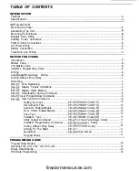
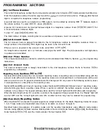
[01] 1st Phone Number .....................................................................................................................

14

1st Account Code ......................................................................................................................

14

2nd Phone Number.. ..................................................................................................................

14

 2nd Account Code .....................................................................................................................

14

Reporting Code Sections 

 to 

................................................................................................

14

Zone Alarm Reporting Codes ....................................................................................................

14

Zone

Reporting Codes ................................................................................................

15

Closing (Arming) Reporting Codes   Partial Closing Reporting Code.. .....................................15
Opening (Disarming) Reporting Codes /After Alarm Reporting Code .....................................16
Priority Alarms and Restorals ....................................................................................................

16

Maintenance Alarms and Restorals.. .........................................................................................

16

Zone Definitions .........................................................................................................................

16

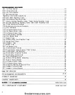
1st System Option Code ............................................................................................................

18

2nd System Option Code ..........................................................................................................

18

3rd System Option Code ...........................................................................................................

19

Communication Variables ..........................................................................................................

19

Zone Bypass Mask ....................................................................................................................

19

System Times

19

Auxiliary Delay Zone Entry/Exit Times .......................................................................................

20

System Clock Times ..................................................................................................................

20

Installer’s Code ..........................................................................................................................

20

Master Code ..............................................................................................................................

20

2nd Master Code .......................................................................................................................

20

Communication Formats ............................................................................................................

21

Programmable Output Options  PGM Terminal ........................................................................

22

Communicator Call Directions ...................................................................................................

23

Downloading Telephone Number.. ............................................................................................

23

Downloading Access Code .......................................................................................................

23

Panel Identification Code ..........................................................................................................

23

Number of Rings Before Answering ..........................................................................................

23

Reset to Factory Default ............................................................................................................

24

4th System Option Code.. ..........................................................................................................

24

5th System Option Code.. ..........................................................................................................

25

Answering Machine Double Call Timer .....................................................................................

25

Installer’s Lockout Enable.. ........................................................................................................

25

Installer’s Lockout Disable.. .......................................................................................................

25

FOR 

THE RECORD

26

PROGRAMMING WORKSHEETS

27-34

HOOKUP DIAGRAM

35

LIMITED WARRANTY

36

NOTES 

FOR 


Inside front cover

FCC COMPLIANCE STATEMENT

Inside rear cover

2

firealarmresources.com

Summary of Contents for PC1150

Page 1: ...is subject to the following two conditions 1 this device may not cause harmful interference and 2 this device must accept any interference received including interference that may cause undesired operation FCC Reg No FSCAN 73151 AL E REN O lB Plug Type RJ31X MADE IN CANADA _ firealarmresources com ...

Page 2: ...utes 4 The User Bypass must be enabled such that a User Code is required to Bypass zones Section 14 light 1 5 The installer should caution the user to not give system information for example Access Codes Bypass methods etc to casual users such as babysitters or home service people Only the One Time use code should be given to the casual user 6 The installer should advise the user and note in the u...

Page 3: ...ditions 7 3 Display Alarm Memory 8 4 Downloading Call up Command 8 5 User Programming Command 9 6 User Function Command 9 Setting the Clock G Master Code l 10 Set Auto Arm Time G Master Code 2 10 Auto Arm Enable Disable G Master Code S 10 Door Chime Enable Disable G Master Code G 10 Siren Test G Master Code 8 10 Installer s Test G Master Code O IO Utility Output Command 7 or 7 Access Code 11 Insta...

Page 4: ...System Option Code 19 Communication Variables 19 Zone Bypass Mask 19 System Times 19 Auxiliary Delay Zone Entry Exit Times 20 System Clock Times 20 Installer s Code 20 Master Code 20 2nd Master Code 20 Communication Formats 21 Programmable Output Options PGM Terminal 22 Communicator Call Directions 23 Downloading Telephone Number 23 Downloading Access Code 23 Panel Identification Code 23 Number of...

Page 5: ... battery l Loss of AC power l Fuse open l Loss of time on system clock l Microprocessor Watchdog circuit Operation Download I Upload capability Programmable auto downloading Swinger shutdown Transmission delay Six Access Codes Master key code All zones programmable as fire zones Programmable test transmission Zone bypass from the keypad Four zones Siren zone Programmable output Four programmable o...

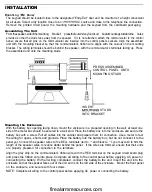
Page 6: ...box opening facing down mount the enclosure in a prepared opening in the wall at least one side of the metal box should be secured to a wall stud Place the battery box into the enclosure and secure the battery box with a screw Pull all cables into the cabinet and prepare them for connection Use a meter to test the wiring for opens shorts and grounds Place the battery into the battery box but do no...

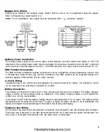
Page 7: ...the switched negative PGM terminal and the AUX terminal AC Power Wiring Completeall wiring to the control panel beforeapplying AC powerorconnecting the battery The transformer should not be connected to an outlet that is controlled by a switch Battery Connection If the battery is connected in reverse the 5 A fuse will open and will need to be replaced The battery charging voltage is factory set an...

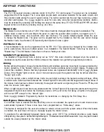
Page 8: ...functions Arming Before arming the panel close all protected doors and windows and stop movement in areas protected by motion detectors If the System light is on check for trouble conditions refer to 2 Display Troubles and correct the condition Ensure that any bypassed zones are bypassed intentionally refer to l Bypass Zones If the Ready light is not on one or more zones are open the system can on...

Page 9: ...y and System lights will be ON if a zone is bypassed Note that fire zones cannot be bypassed Enter I to display the bypassed zones theZone Lights of bypassed zones will come ON Ensure that any zone displayed as being bypassed is intentionally bypassed Zone bypasses are automatically cancelled when the panel is disarmed To Bypass Zones Enter l the System light will start flashing Enter the number o...

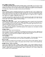
Page 10: ...s of time trouble will notbe generated if the Test Transmission and Auto Arm times are not programmed NOTE If 9 is pressed while in the Display Trouble Conditions mode the last set of trouble conditions will be displayed on the zone lights This trouble memory is useful as a diagnostic tool when installing and servicing the PC1 150 3 Display Alarm Memory Alarms caused during the previous armed peri...

Page 11: ...igit Access Code do not press or when entering the code After the code is entered the keypad will beep 3 times and the zone light will stop flashing and remain ON If you are changing an existing code the new code will replace the old one If you wish to program another code press the number key for the code to be programmed and enter the new Qdigit code Press the Key to return to ready Erasing a Co...

Page 12: ...ter Code S NOTE For UL installations the Auto Arm feature must always be disabled When this feature is enabled the system will automatically arm at the same time each day The time for Auto Arming may be programmed in Section 19 or set using the G Master Code 2 Set Auto Arm Time command When the feature is being enabled the keypad will sound 3 quick beeps when 5 is pressed When the feature is being...

Page 13: ...g the status of the system This feature must be enabled for it to be operational Quick Exit may be enabled at Section 32 Light 4 After O is entered only one armed delay zone may be opened within 2 minutes Any additional openings or openings after the 2 minute delay will cause an alarm Keypad Zones There are three zones which can be activated by pressing and holding two keys on the keypad For these...

Page 14: ...icate that the expected data has been entered When asection iscompletely programmed enter the number of the next Section that is to be programmed It is not necessaryto program all 2 digit numbers in any given Section ASection can be entered and selectively programmed by going only to the digits you wish to change After your changes have been made press the Key to return to the programming mode You...

Page 15: ...t HEX numbering uses the digits 0 through 9 and the letters A through F The letters A through Fare represented by the number keys 1 through 6 To enter data in HEX format first press the Key The Ready light will FLASH Enter the HEX value then press the I Key again to return to the normal data entry mode the Ready light will stop flashing To enter HEX numbers A Enter J l B Enter 2 C Enter 3 D Enter ...

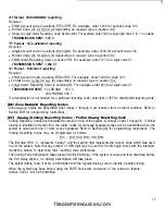
Page 16: ...nd telephone number Refer to Section 02 for programming instructions Reporting Code Sections 05 to CiO Sections 05 to lo contain the communicator reporting codes A reporting code is transmitted along with the account code with each transmission If the reporting codes are not programmed no transmission will be sent when an event occurs To prevent a transmission from being sent for any event in the ...

Page 17: ...ne Restoral Codes are transmitted when zones 1 through 6 are restored from an alarm condition Refer to Section 05 for programming instructions 1071 Closing Arming Reporting Codes Partial Closing Reporting Code Closing Reporting Codes are transmitted to identify arming of the system by Access Codes 1 through 6 If Partial Closing is identified in Section 14 the alarm codes for manually bypassed zone...

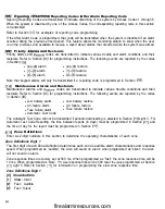
Page 18: ...es are transmitted to indicate various trouble conditions and their restorals Refer to Section OSJ for programming instructions The following events are reported by the codes in Section IO l Low battery alarm l Low battery restore l AC failure alarm l AC failure restore l Fuse failure alarm l Fuse failure restore l Automatic Test Code The Automatic Test Code will not be transmitted if periodic dow...

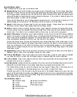
Page 19: ... Home Away zones can have the Entry Delay when Section 32 Light 3 is ON When Light 3 is ON the Entry Delay will be applied to all Interior Home Away zones when the system is armed and the Interior zones are not bypassed If the Interior Home Away zones are automatically bypassed or are bypassed by arming with the 9 command the user may enter I to make the Entry Delay apply to the Interior Home Away...

Page 20: ...y light A Armed light l Factory default settings m DTMF dialling will default to pulse dialling after 2 unsuccessful DTMF dialling attempts v Must be programmed for UL installations 13 2nd System Option Code Refer to Section 12 for programming information LIGHT Al l ON Zone 4 N O without EOL OFF Zone 4 is normal PI ON Master Code not user changeable l OFF Master Code user changeable 31 ON Siren sq...

Page 21: ... zone before the communicator shuts down for that zone The number of attempts is for the period defined in Section 12 1st System Option Code Light 2 The number of communication attempts may be programmed from 00 to 99 where 00 means the communicator will never shut down Note that the fire zone cannot be shut down it always transmits 16l Zone Bypass Mask Refer to Section 12 for programming informat...

Page 22: ...atures time of day in the 24 hour clock format must be programmed for these features to function Avalid Test Transmission or Periodic Downloading is enabled in Section 14 3rd System Option Code Light 3 The cycle time in days for the test transmission or periodic downloading is set in Section 17 System Times For atest transmission using the communicator an automatic test code should be entered in S...

Page 23: ...rmats 3 l 412 non extended formats 4 Radionics 5 Do Not Use S Do Not Use f71 Do Not Use 2300 l 400 Hz 3 l 4 2 non extended with parity format 8 Silent Knight Ademco Slow 10 bps 1400 Hz 3 l extended format 9 Sescoa Franklin DCI Vertex 20 bps 2300 Hz 3 l extended format A Silent Knight Fast 20 bps B Radionics C Radionics 1400 Hz 2300 1400 Hz 2300 1400 Hz 3 l extended format 3 l extended format 3 l e...

Page 24: ...F5 trouble from source 5 l Miscellaneous D For example Dl partial closing 24 Programmable Output Options PGM Terminal The PGM output can be programmed to operate in response to various panel operations The output pulse connects the PGM terminal to the negative power rail WI PI 031 041 WI WI WI Not Used Utility Output no Access Code Whenactivated byenteringthe 7 command thePGMoutputwill golowfor5se...

Page 25: ...number when Section 13 Light 1 is OFFand the panel has made 8 unsuccessful attempts on the 1st phone number 2 Call the 2nd phone number only 3 Always call both phone numbers NOTE If the Key is pressed during data entry the keypad will return to the Installer s Programming Mode and any data entered in this section will not be saved 2g Downloading Telephone Number Enter the Downloading Telephone Num...

Page 26: ...ring machine over ride 41 ON System light flashes when armed to indicate alarm memory l OFF System light normal RI ON Quick Arm enabled l OFF Quick Arm disabled Al ON Restore on siren time out if zone is restored l OFF Restore as follower when zone restores R Ready light A Armed light l Factory default Downloading and Answering Machines The answering machine override feature allows an answering ma...

Page 27: ...h of time between the first and second calls when using the answering machine override feature FOj Installer s Lockout Enable With this feature enabled the Installer s Code and Downloading Access Code will not be restored to the default setting when the panel s programming is restored to its default settings through a software or hardware reset This feature is designed to prevent tampering with th...

Page 28: ...3 digit code enter 0 for the 4th digit 2nd Phone Number Page 14 2nd Customer Account Code Page 14 Zone Alarm Reporting Codes Page 14 For single digit reporting codes enter 0 as the second digit Default 3 1 l l Zone 1 Alarm Enter l HEX A to transmit a 0 zero IO pulses 3 2 Zone 2 Alarm L 3_ Zone 3 Alarm t_L_L Zone 4 Alarm Zone Restoral Reporting Codes Page 15 For single digit reporting codes enter 0...

Page 29: ...ng if an alarm occurred during the previous armed period Access Code 1 Access Code 2 IAccess Code 3 Access Code 4 1 Access Code 5 i__u Access Code 6 IAfter Alarm Code Priority Alarms Restorals Page 16 Actuation of the keypad zones will immediately transmit both an alarm and restoral code There is no delay on the restoral code transmission Default u Not Used L22LE l I Alarm ULL 1 3 Alarm l U 4 6 Al...

Page 30: ...Digit 2 o o Zone 1 0 Slow Audible 0 1 Slow Silent 1 l U Zone 2 2 Fast Audible 2 a 3 Fast Silent 3 Zone 3 4 0 1 Zone 4 5 6 7 1st System Option Code Page 18 Default Zone Light ON ON Zone Light 1 Communicator disabled Standard Delay Instant Interior Interior Home Away 24 Hour Siren 24 Hour Siren Buzzer 24 Hour Buzzer Auxiliary Delay Zone Light OFF Communicator enabled oFF I Zone Light 2 TX limit to 2...

Page 31: ...Zone Light 3 Periodic downloading oFF Zone Light 4 c 4 access code required ON Ready Light Planic audible buzzer oFF Armed Light Partial closing identified Communication Variables Page 79 Default zi_l Maximum transmissions per burglary zone Zone Light OFF Code not required 4 Disabled Periodic test transmit I 4 no code required Planic silent Not identified Enter digits from 01 to 99 for number of t...

Page 32: ...entries are 001 to 255 System C ock Times Page 20 Default 9 9 9 9 I I I 1 Automatic Arming time of day 9 9 9 9 l Test Transmission or Auto Download time of day Enter time in 24 hour clock format If not used program as 9999 to disable NOTE For UL installations the Auto Arm feature must always be disabled Installer s Code Page 20 Default 1 2 1 2 1 Master Code Page 20 Default 1 2 3 4 For Sections 20 ...

Page 33: ...ent Knight Ademco Slow 10 bps 1400 Hz 9 Sescoa Franklin DCI Vertex 20 bps 2300 Hz A Silent Knight Fast 20 bps 1400 Hz B Radionics 2300 1400 Hz 3 l extended format 3 l extended format 3 l extended format 3 l extended format Cl Radionics 2300 1400 Hz 3 l extended with parity format D Do Not Use El Do Not Use Fl Do Not Use l See Section 13 for Radionics handshake option 1241 Programmable Output Optio...

Page 34: ...umber is used by the panel to call the downloading computer either by the periodic download function or through the use of the I 4 command Refer to Section Ol for information on programming telephone numbers Downloading Access Code Page 23 Default This code allows the panel to confirm that a valid downloading computer is requesting access to the panel Panel Identification Code Page 23 Default This...

Page 35: ...ed 1321 5th System Option Code Default oFF Zone Light 1 Page 25 Zone Light ON AC excluded from trouble ON Zone Light 2 No siren during auto arm Siren during auto arm oFF Zone Light 3 Home away with delay Home away as interior ON Zone Light 4 Quick exit enabledm Quick exit disabled oFF Zone Light 5 Force arm on auxiliary delay Auxiliary delay normal oFF Zone Light 6 60 s bypass on power up Zones ac...

Page 36: ...firealarmresources com ...

Page 37: ...l be in lieu of any and all other warranties whether expressed or implied and of all other obligations or liabilities on the part of Digital Security Controls Ltd This warranty contains the entire warranty Digital Security Controls Ltd neither assumes nor authorizes any other person purporting to act on its behalf to modify or to change this warranty nor to assume for it any other warranty or liab...

Page 38: ...s all connections to the telephone network shall be made through standard plugs and telephone company provided jacks or equivalent in such a manner as to allow for easy immediate disconnection of the terminal equipment Standard jacks shall be so arranged that if the plug connected there is withdrawn no interference to the operation of the equipment at the customer s premises which remains connecte...

Reviews: