5
Section 3: CFP-500 Operation
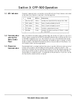
3.1 LED Indicators
The dialer’s operating status is visible from its five LED indicators. These indicators are located
on the dialer. Each indicator is described in the following table:
3.2 Communication
with the Fire
Alarm Control
Panel
When connected to the FACP properly, the Watchdog LED will flash at a rate of ½ second on/
off when power is applied to the FACP. The dedicated dialer will transmit all events that occur
on the FACP if programmed to do so. Any troubles that occur on the dedicated dialer will be
shown on the appropriate LED and communicated (if enabled) as well as causing a common
trouble condition on the FACP. If the FACP should lose communication with the dialer a com-
mon trouble condition will also be generated.
3.3 Phone Line
Communication
The dedicated dialer is equipped with two phone line connections. When an event occurs that
initiates communications, the first attempt at dialing will be on telephone line #1. If the
attempt fails, the dialer will then select telephone line #2 for the next attempt at dialing. This
will continue until the maximum number of dialing attempts is reached. Please note that on
the first attempt to telephone line #1, if a telephone line trouble exists on line #1 and not line
#2, then the first attempt will start on line #2.
#
Indicator
LED Color
Activates when...
1
Secur-bus Fault
Yellow
the Secur-bus connection to the main panel has failed
2
TLM2 Trouble
Yellow
there is a trouble on telephone line #2
3
TLM1 Trouble
Yellow
there is a trouble on telephone line #1
4
FTC Trouble
Yellow
the dialer is unable to communicate
5
Watchdog
Green
the dialer is functioning normally; LED flashes ½ second
on, ½ second off
firealarmresources.com
Summary of Contents for CFP-500
Page 31: ...firealarmresources com ...


