


English
I NS TAL LAT ION M ANUA L
Ø
Attach the first round concentric pipe piece to the adapter using 4 self-drilling screws.
Ø
On this connection, apply a clip binding with silicon sealing ring.
Ø
In case of round pipe pieces, attach a clip binding with silicon sealing ring to each connection.
Ø
Use a self-tapping screw to fix the clip binding to the pipe on locations that cannot be reached after installation.
Ø
In case of round pipes, apply sufficient brackets, so that the weight of the pipes does not rest on the appliance.
Ø
Determine the remaining length of the wall terminal;
Ø
Make sure the wall terminal has the right dimensions.
!Caution
-
Make sure that the right insertion length is maintained;
-
Place the wall terminal with the groove/folded seam at the top;
-
Make sure the horizontal concentric pipe pieces are sloping towards the wall terminal, in order to prevent
rain water from entering.
Ø
Mount the rosette (mounting inner plate); if necessary, on a heat resistant intermediate plate when passing
through combustible material.
Ø
Attach the wall terminal from the outside with four screws in their respective holes.
5.4.3 Application with roof terminal
The roof terminal is a round concentric system.
5.4.3.1 Construction of concentric system with roof terminal
The concentric system with roof terminal has to comply with the following conditions:
-
The construction of the chosen system has to be allowed. (See the procedure described below);
-
First, a concentric pipe of at least 1 meter should be connected vertically to the appliance.
Depending on the construction of the concentric system, the appliance is set by:
-
placing the Restrictor slide and/or
-
removing the air inlet guide.
In the following procedure you can see how the allowability of a concentric system can be determined and
which settings are needed.
Ø
Determine the following data:
1) The number of bends required (no distinction is made between 45° and 90° bends);
2) The total number of meters of horizontal pipe length;
3) The total number of meters of vertical and/or sloping pipe length (roof terminal excluded).
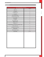
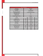
With these data and Table 5 you will be able to determine whether the concentric system is allowed.
In Table 6 you can see which setting the appliance requires.
Follow the procedure described below:
Ø
In the first 2 columns of Table 5, look for the number of bends required and the total horizontal pipe length.
Ø
In the 3rd column of Table 5, look for the total vertical and/or sloping pipe length.
If you end up in a box with the letter A, B, C, or D the concentric system chosen by you is allowed.
Ø
Use Table 6 to determine which conditions apply for the Restrictor slide and/or the air inlet guide (for setting,
see section 5.7).
5.4.3.2 Placing concentric system with roof terminal
The roof terminal can end in a sloping and a flat roof.
The roof terminal can be supplied with an adhesive plate for a flat roof or with a universally adjustable tile for a
sloping roof. In case of a sloping roof with a slope up to 24°, it is also necessary to use an adhesive plate.
UK
Summary of Contents for G20
Page 28: ...E n g l i s h INSTALLATION MANUAL UK A C B C 38c 1461 A B 38c 1 462 3a 2 3b 3c ...
Page 32: ...E n g l i s h INSTALLATION MANUAL UK E 38p 0029 A B C D A 38p 0030 B 38p 0031 10a 10b 10c ...
Page 33: ...E n g l i s h INSTALLATION MANUAL UK C 38p 0032 D 38p 0033 E 38p 0034 10d 10e 10f ...
Page 34: ...E n g l i s h INSTALLATION MANUAL UK 38p 0035 38p 0062 10g 10h ...
Page 37: ...E n g l i s h INSTALLATION MANUAL UK 38p 0181 5mV 38p 0182 20mm 25mm 38c 1471 1 16 17 18 ...
Page 38: ...E n g l i s h INSTALLATION MANUAL UK ...