DROPSA VIP4ToolsPro User And Maintenance Manual Download Page 8


7.6  

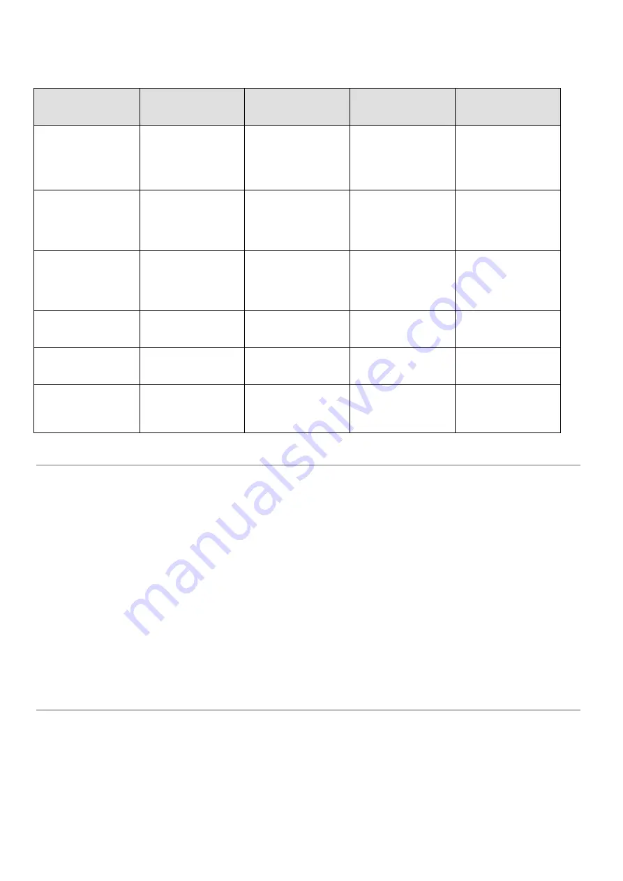
APPROXIMATE CONSUMPTION FOR LRT OILS  (3226661) USAGE 


Grams per lubrication nozzle in 8 hours operating time 


ALUMINIUM 

LEADED BRASS 

LEADED STEEL 

SOFT STEEL 

ALLOY STEEL 

STAINLESS STEEL 

REFRACTORY 

AND TITANIUM 

ALLOYS 

 
Saw cutting 
Turning 
Shearing 
Cutting off 

35-40 

30 

30 

30-60 

 
Boring 
Drilling 
Milling 
Slotting 

30-40 

30 

60 

70 

 
Threading 
Tapping 
Planing 
Shaving 

60 

70 

80 

90 

 
Threading blind 
tapping 

60 

70 

80 

90-100 

 
Moulding and 
standard drawing 

60 

70 

80-90 

90-100 

 
Broaching 
Toothing 
Bending 

70 

80 

90 

100/110 


8. MAINTENANCE 


The pump has been designed and constructed so as to reduce maintenance to a minimum. 
To simplify maintenance it is recommended that the equipment be mounted in an easily reached location 

(see paragraph 6.2)

Periodically check the tubing connections for leaks. Always maintain the equipment in a clean condition in 
order that any leaks will be immediately evident. 
When necessary replace the oil filling filter P/N 3130139. 
Periodically  empty  the  pressure  regulator  condensate  trap  by  rotating  the  small  red  valve  located  at  its 
base. 
The  machine  does not  require  any  special  tools  for  carrying out  checks and/or  maintenance  tasks.  It  is 
recommended  that  suitable  tools  and personal protection  clothing  (gloves) are  used  in  accordance  with 
current  regulation(Safety  at Work  legislation),  and  that  they  are  in  good  condition  (according  to  current 
regulation) in order to avoid injury to persons and damage to the machine. 
 

Ensure that electrical, pneumatic and hydraulic supplies are disconnected before undertaking any 
maintenance tasks.


9. DISPOSAL 


During  the  maintenance  of  the  machine,  or  in  the  event  of  its  being  scrapped,  do  not  discard  polluting 
components  in the  environment.  Refer  to  local  regulations for  their  correct  disposal.  At  the  time  of final 
disposal of the machine it is necessary to destroy the identification plate and all other documentation. 


Summary of Contents for VIP4ToolsPro

Page 1: ...STRUCTIONS FOR USE 8 MAINTENANCE 9 DISPOSAL 10 ORDERING INFORMATION 11 DIMENSIONS 12 HANDLING AND TRANSPORTATION 13 PRECAUTION IN USE 14 CONTRAINDICATIONS http www dropsa com Via Benedetto Croce 1 Vim...

Page 2: ...mmediately replaced After long periods of inactivity check air tightness of all parts subjected to pressure Personnel must use personal protection equipment clothing and tools adequate for the locatio...

Page 3: ...re 10 C 80 C 14 F 176 F Maximum switching power 50 W 5 V Maximum current 1 A Maximum voltage 220 V AC 5 DESCRIPTION OF COMPONENTS Central VIP4ToolsPro Unit The central unit of the lubrication system i...

Page 4: ...r on components subject to vibration Only use the supplied mounting bracket with N 2 holes for 6 mm 0 23 in bolts 6 3 MOUNTING THE MINI PUMPS ON THE MIXER BASES for replacement or augmenting The mini...

Page 5: ...ecifications 6 6 1 Schematic electrical connection Samba Level NC electric level in the absence of lubricant 6 6 2 Schematic electrical solenoid connection Connector 39979 EV 24 V DC non polarized N B...

Page 6: ...6 EXAMPLE OF TUBING AND NOZZLE CONNECTION STRAIGHT TUBING CO AXIAL TUBING CONNECTION...

Page 7: ...s to an increase in flow of 5 mm until reaching 30 mm at the 7th turn see table FLOW mm stroke TURNS 30 6 5 25 5 5 20 4 5 15 3 5 10 2 5 5 1 5 0 no pump delivery Completely unscrewed 7 4 OUTLET AIR FLO...

Page 8: ...rder that any leaks will be immediately evident When necessary replace the oil filling filter P N 3130139 Periodically empty the pressure regulator condensate trap by rotating the small red valve loca...

Page 9: ...rication Points with pneumatic timer 3 Liters 24V AC 50 60Hz 3704320 2 Lubrication Points with pneumatic timer 3 Liters 24V AC 50 60Hz 3704330 3 Lubrication Points with pneumatic timer 3 Liters 24V AC...

Page 10: ...IR FLOW REGULATOR SOLENOID VALVE 24 V DC AIR SUPPLY Push in 8 tubing LUBRICANT EXIT 6 3 co axial 4 Mono tubing PUMP STROKE ADJUSTMENT AIR FLOW REGULATIOR ELECTRIC LEVEL FILLER PLUG SOLENOID CABLE GLAN...

Page 11: ...electronic tank and base structure must be connected to the ground line see paragraph 6 7 Flammability The oil employed in the lubrication circuit is not normally flammable It is nonetheless indispen...

Page 12: ...The operator coming into contact with fluid due to breakage opening of supply tubing The operator must be furnished with suitable personal protection clothing equipment according to current regulation...

Reviews: