background image

C20008IE – Pneumatically driven pump  -  Rev. 0                February 99                 Page 4 of 9                  

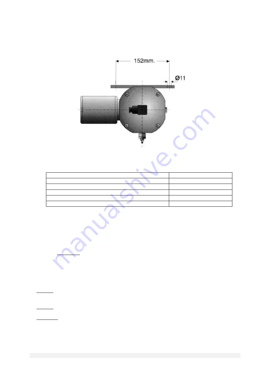
2.2 

Fixing dimensions 


2.3  

Other data 


NLGI grease rating at working temperature 

see table at sub-section 4.0 

Viscosity of the lubricant at working temperature 

Between 15 - 2000 cSt 

Working temperature 

+ 5 - + 80 

°

Working humidity 

90 % relative humidity. 

Preservation temperature 

- 20 - + 50 °C 

Sound pressure level  

< 70 dB(A) 


3.0 

CORRECT USE 


3.1 

Putting into service 


♦  

The unit may be used, opened and repaired only by specialised personnel. 


♦  

The pump MUST NOT be submersed in fluids or utilised in environments which are particularly aggressive or 
explosive/inflammable if not prepared for this purpose beforehand by the supplier. 


♦  

For correct fixing verify the distance between centres shown in the diagram in Section 2.2. 


♦  

Use gloves and safety glasses as required in the lubrication oil safety chart. 


♦  

DO NOT use aggressive lubricants with NBR gaskets and seals; if in doubt consult the Engineering Department 
of Dropsa SpA, who will provide a chart with the details of recommended oils. 


♦  

DO NOT ignore dangers to health and observe all hygiene standards. 


♦  

WARNING! All electrical components must be grounded. This refers to both electrical components and control 
devices. In this regard ensure that the ground cable is correctly connected. For reasons of safety the ground cable 
must be approx. 100 mm longer than the phase cables. In the event of accidental detachment of the cable, the 
ground terminal must be the last to be removed.


Summary of Contents for 3103014

Page 1: ...WARNING 1 0 DESCRIPTION OF THE PUMP 2 0 TECHNICAL SPECIFICATIONS 3 0 CORRECT USE 4 0 INSTRUCTIONS FOR ORDERING AND DISTRIBUTORS DECLARATION OF CONFORMITY Catalogue P N C2008IE Wk 05 99 Registered nam...

Page 2: ...ubject the pump the tubing or other parts under pressure to violent impacts damaged tubing or connections are dangerous and should be replaced After prolonged periods of inactivity ensure the tightnes...

Page 3: ...ECIFICATIONS 2 1 Methods of commanding the pump Manual push button control 3 way solenoid valve control Mechanical roller or cam bar control Supply Supply Supply Discharge Discharge Discharge C20008IE...

Page 4: ...this purpose beforehand by the supplier For correct fixing verify the distance between centres shown in the diagram in Section 2 2 Use gloves and safety glasses as required in the lubrication oil safe...

Page 5: ...r at a minimum temperature of 5 C 3 4 Assembly Disassembly No pump assembly operations are envisaged For wall or floor mounting ensure adequate space is available as shown in the installation diagram...

Page 6: ...mbly The following should be checked periodically VERIFY WORK CYCLES The state of lubrication 100 The oil level 200 The cleanliness of the suction filter 400 The cleanliness of the loading return filt...

Page 7: ...Machine Directive is effected by means of the compilation of a check list which has been pre prepared and is contained in the technical file The lists which are utilised are of three types list of dan...

Page 8: ...NLGI1 30 1 5 0 5 2 YES 3413014 Pneum S A NLGI1 30 1 10 0 5 2 NO 3413016 Pneum S A NLGI1 30 1 5 0 5 2 YES with loading filter 3413018 Pneum S A NLGI1 30 1 3 0 5 2 YES 3413019 Pneum S A NLGI3 30 1 10 0...

Page 9: ...RECTIVE OF THE COUNCIL OF THE EUROPEAN COMMUNITY concerning the harmonisation of member states legislation relative to machines 89 392 CEE 91 368 CEE EMC 89 336 CEE and BT 73 23 CEE and relative amend...

Page 10: ......

Page 11: ......

Reviews: