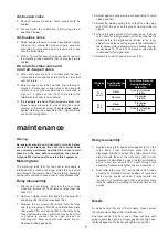
8.
Coil stop adjusted to allow approximately (0.8 mm)
(1/32”) flapper travel in front of nozzle.
9.
All mechanism components fastened firmly as
required.
10. Proper nozzle size selected. Number of nozzle
stamped on body of nozzle. The table below
indicates nozzle number for each utilization case.
Pneumatic circuit
In the event of faulty operation of the positioner, where
the cause is not readily apparent, check air system as
follows :
1.
Exert sufficient force on the flapper to cover the
nozzle. Valve stem should travel its full stroke.
2.
If response is other than indicated in the above
steps, push cleanout plunger of metering orifice,
Inspect for plugged nozzle. Check to see if metering
orifice body is properly seated in the relay. If difficulty still
persists, disassemble and clean relay.
Electrical circuit
After checking pneumatic circuit, the electrical circuit
should be checked with an ohmmeter as follows:
1.
Disconnect signal leads from terminal board S/A.
2.
Connect ohmmeter leads to positioner terminal
board leads and check positioner circuit resistance
with nominal resistance indicated on identification
plate. Table of Figure 4 of the Instruction sheet No
ES 50004-000 E shows the nominal resistance of
main circuits.
3.
Disconnect coil lead from positive terminal and
connect to one of the ohmmeter leads. Connect
other ohmmeter lead to negative terminal. Force coil
resistance value should approximate value indicated
in table of Figure 4 of Instruction sheet No
ES 50004-000 E.
4.
If force coil resistance is approximately correct but
positioner circuit resistance is not, repair or replace
terminal board. If force coil resistance is not correct
replace force coil.
5.
Remove ohmmeter lead from negative terminal and
connect it to coil stop screw. Check for short in force
coil.
Replace the coil if ohmmeter indicates a value other
than very high resistance (practically infinite).
Supply
Pressure
150 to
300 mm
(6” to 12”)
80 and
100 mm
(3” and 4”)
25 to
50 mm
(1” to 2”)
psi
m bar
Nozzle Number
Valve size
20
15
25
15
30
15
13
35
13
40
12
45
12
50
12
55
12
60
12
65
11
70
11
75
*
Only on 100 mm (4”) valve size
1400
1700
2100
2500
2800
3100
3500
3800
4200
4500
4800
5200
11
12
12
11
11
11*
11*
On Valves Camflex II
Supply
Pressure
No 3
No 5
No 7
No 9
psi
m bar
Nozzle Number
Actuator size
20
25
30
14
15
15
15
15
15
11
11
15
35
40
45
50
11
11
11
11
11
11
11
11
11
55
60
65
70
75
1400
1700
2100
2500
2800
3100
3500
3800
4200
4500
4800
5200
12
14
11
11
12
14
14
14
14
14
14
14
11
11
12
12
12
12
12
12
12
12
12
12
On Varimax Valves
August 1997


