background image

Air-to-open valve

5.

Shut-off supply pressure. Valve plug should be
seated.

6.

Proceed with the calibration, performing step 9
described  below.

Air-to-close valve

7.

Adjust supply pressure to proper requirement (psig).
(See valve catalog for proper supply pressure
according to valve size and to pressure drop; see
also the serial plate).

8.

With a 10 mm flat wrench unscrew about one turn
the metering tube assembly (59) until valve plug is
seated.

On an air-to-close valve and 

on an air-to-open valve

9.

When the valve stem is in contact with the seat
(valve seated) loosen the screw (160) in order that
cam will rotate.

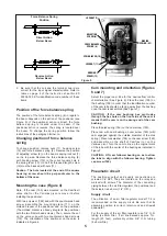
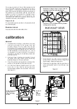
10. Select proper cam lobe and lobe line referring to

Figure 6. Rotate cam to align proper lobe line with
center of cam follower bearing as indicated in
Figure 7. Tighten screw (160) to maintain the
relation-ship of cam to cam follower.

11. If air supply is shut off (air-to-open valve) then

adjust supply pressure to proper psig (see valve
catalog or the serial plate). If air-to-close valve,
tighten metering tube assembly (59). (Tighten firmly
but do not overtighten).

12. Adjust signal to proper value corresponding to valve

closed position.

13. Adjust the biasing spring (52) so that the valve plug

will lift off the seat at the proper closing milliamp
signal.

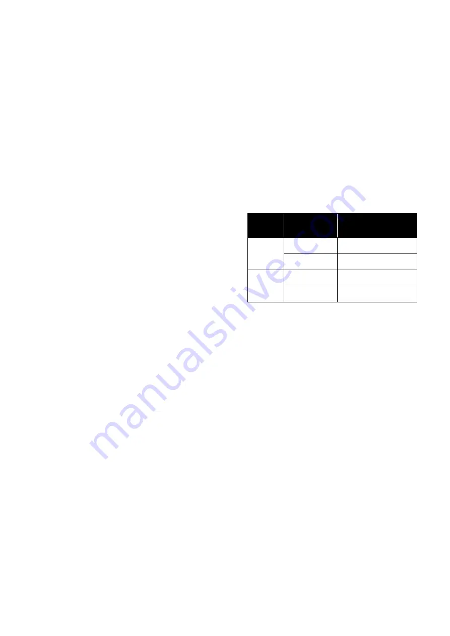
14. Check full valve stroke for full signal span. If stroke

is too short for full signal span or if valve reaches full
stroke before full signal span (stroke is too long)
adjust force balance spring screw (6) as indicated in
table below. After adjusting force balance spring,
repeat steps 12, 13 and 14 until proper valve stroke
is obtained for full signal span.

15. Assemble cover (3) and cam cover (151).

7

maintenance

Warning :

De-energize electric and pneumatic circuits before
service or maintenance. Be sure that connections
are correctly performed and that the cover is well
placed on the case before energizing the circuits.
Only qualified personnel to service this equipment.

Metering tube

The metering tube (59) for the nozzle air supply is
furnished with a clean-out plunger which forces a small
wire through the jewel orifice. The metering assembly
can be removed and checked prior to relay disassembly.

Relay disassembly

1.

Disconnect air tubing. Unscrew the four relay
mounting screws (21) and remove relay from the
case (14).

2.

Remove holding screw (69) and drop the plug (67)
and spring (68) from the relay body (66).

3.

Remove the six screws (53) which hold the relay
cap (54), diaphragm S/A (55) and Bellofram plate
(56), gasket (57) and spring (58) to the relay body.
Clean parts with a clean soft cloth. Use solvent if oil
or grease is present (do not use solvent on
diaphragms). Blow out parts with clean dry air.
Replace all damaged parts.

Relay reassembly

1.

Replace spring (58) and position gasket (57) on the
relay body. Place Bellofram plate S/A (56),
diaphragm S/A (55) and cap (54). Align holes in this
elements with those of the relay body (66). Correct
alignment is simplified by use of external reference
mark. Insert two screws 180° apart through this
assembly. Replace and tighten the six screws (53).

2.

Assemble relay plug (67), spring (68) and holding
screw (69). Establish correct position of relay and
fasten on the positioner case. If relay repairs are
required it is recommended that a new temporary
relay be adapted, permitting to minimize time out of
service.

Nozzle

To clean nozzle (16) shut off air supply ; loosen screw
(45) and remove flapper (46) from beam (41).

Unscrew nozzle (16) from case. Clean out hole with
solvent and clean dry air. Screw nozzle into the case,
replace flapper on the beam and tighten screw (45).

If Stroke

is :

And Positioner

Action is :

Turn Force Balance

Spring Adjusting

Screw (6) :

Too

short

Direct

Counter clockwise

rotation

Reverse

Clockwise

rotation

Too

long

Direct

Clockwise

rotation

Reverse

Counter clockwise

rotation

Summary of Contents for Masoneilan 8013 Series

Page 1: ...Masoneilan 8013 series Electropneumatic positioner Instructions used with 35002 series CamflexII and 30000 series Varimax control valves Instructions No ES50004 250E Rev B 08 97 Masoneilan Masoneilan ...

Page 2: ...ent of Condé sur Noireau Plant Any future orders for spare parts should be addressed to the Spare Parts Department of our factory at Condé sur Noireau When such an order is placed you should always cite in reference the original order and in particular the type and the serial number of the positioners involved Training MASONEILAN regularly holds training seminars for technicians in its factory of ...

Page 3: ...truction sheet No ES50004 000 E page 3 c In case of flameproof housing device the positioner case must not be opened when the device is energized d Reverse the force balance spring position in regard to the beam see corresponding paragraph of page 5 e Calibrate after changing of action f Consult the instruction sheet No ES50004 000 E 3 split range operation The following instructions apply only wh...

Page 4: ...ectly performed and that the cover is well placed on the case before energizing the circuits Only qualified personnel to service this equipment Checking 1 Check the number stamped on the nozzle 16 Nozzle size depends on valve size and the supply pressure Refer to the table on the last page for the numbers of the nozzle corresponding to each use Controller Positioner N 1 Positioner N 2 Controller P...

Page 5: ...ositioner on the valve is indicated in Figure 4 Cam mounting and orientation Figures 6 and 7 Select the proper cam lobe for the desired flow control characteristics See Figure 6 Place the cam 155 on the bushing 159 in order that the identification number of the cam lobe should be facing away from the bushing once the cam is assembled See Figure 7 CAUTION If the cam bushing hex protrudes through th...

Page 6: ... 4 Turn the force balance adjusting screw 6 on the beam 41 in order that the spring should be approximately parallel to the joint plane of the case see Figure 5 6 calibration 3 4 5 6 1 2 Masoneilan Masoneilan 160 156 155 151 158 159 155 160 5 Center of cam follower bearing Figure 7 Proper alignment line for Lobe 5 with valve plug seated 3 4 5 6 1 2 12 1 1 1 0 9 8 7 Figure 6 Masoneilan Masoneilan 1...

Page 7: ...correctly performed and that the cover is well placed on the case before energizing the circuits Only qualified personnel to service this equipment Metering tube The metering tube 59 for the nozzle air supply is furnished with a clean out plunger which forces a small wire through the jewel orifice The metering assembly can be removed and checked prior to relay disassembly Relay disassembly 1 Disco...

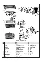
Page 8: ...w 30 Serial Plate 32 Force Balance Spring Lever 33 Release Spring 39 Biasing Spring Bracket 40 Coil 41 Beam 42 Screw Flexure Strips 43 Stop Locknut 44 Coil Stop Screw 45 Screw Fastening Coil and Flapper 46 Flapper 48 Counter Weight 49 Flexure Strip 50 Flexure Strip 52 Biasing Spring 53 Mounting Screw relay 54 Relay Cap 55 Diaphragm S A 56 Bellofram Plate S A 57 Gasket 58 Spring 59 Metering Tube S ...

Page 9: ...en stop locknut 43 Reattach force balance spring 8 on adjusting screw 6 7 Connect coil wires to terminal board according to the desired positioner action Proceed to calibration and replace cover Terminal board replacement If it becomes necessary to change the input signal range of a positioner a terminal board and coil adapted to accommodate the new signal should be ordered from the Spare Parts De...

Page 10: ...S 50004 000 E shows the nominal resistance of main circuits 3 Disconnect coil lead from positive terminal and connect to one of the ohmmeter leads Connect other ohmmeter lead to negative terminal Force coil resistance value should approximate value indicated in table of Figure 4 of Instruction sheet No ES50004 000 E 4 If force coil resistance is approximately correct but positioner circuit resista...

Page 11: ...of their respective owners 2014 General Electric Company All rights reserved Visit our web site www fr eps com E P S FRANCE 24 bis rue de Picpus 75012 PARIS Tel 33 0 762 682 291 Tel 33 0 650 590 965 ventes fr eps com E P S CAMEROON Immeuble Carré d Or Rue Soppo Priso Côté Chococho Bonapriso DOUALA Tel 237 6 52 12 70 95 Tel 33 0 782 006 276 ventes fr eps com ...

Reviews: