2.
Be sure that the coil and the terminal board are
correct for the input signal characteristics. Refer to
table on page 4 of the instruction sheet No ES
50004-000 E for identification code number of these
items.
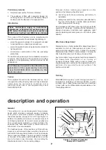
Position of the force balance spring
The position of the force balance spring (8) in regard to
the beam depends on the action of the positioner (see
Figure 5). If the positioner action is direct, the force
balance spring is located under the beam. If the
positioner action is reverse, the spring is located over
the beam. To change the spring position follow the
instructions of the paragraph further on.
Changing position of force balance
spring
To change position, remove nuts (11), hooking screw
(12) and force balance spring (8). Reverse the position
of adjusting screw (6) on the beam keeping locknut (7)
on the top side. Replace the force balance spring (8)
with hooking screw (112) in the correct square hole in
the spring lever (10). On half its threaded length, screw
(12) must be blocked with nuts (11).
Caution : The hole located at the end of the square
hooking screw should be perpendicular to the
bottom of the case.
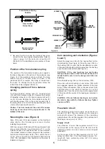
Mounting the case (Figure 4)
Note : If the cam (155) was mounted on the Camflex II
valve shaft or the Varimax pivot, remove it before
installing the positioner.
With two screws H (152) and with the countersunk head
screw, assemble the mounting plate (171) on the
molded bracket of the positioner and on the positioner
(The molded bracket is already integral to the positioner
with the two fillister-head screws). Then, secure the set
on the valve yoke with two countersunk head screws
(172). The orientation of the positioner on the valve is
indicated in Figure 4.
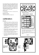
Cam mounting and orientation (Figures
6 and 7)
Select the proper cam lobe for the desired flow control
characteristics. (See Figure 6). Place the cam (155) on
the bushing (159) in order that the identification number
of the cam lobe should be facing away from the bushing
once the cam is assembled (See Figure 7).
CAUTION : If the cam bushing hex protrudes
through the hex hole on the front side of the cam it
means that the cam is on the wrong end of the cam
bushing.
Place the disk spring (156) on the cam screw (160).
Place cam with cam bushing on cam screw (160) (with
cam engaged against the outside diameter of the disk
spring). Place lock washer (158) on the cam screw (160)
and assemble on the shaft of Camflex II or on the
Varimax pivot. Turn the cam to line-up the original mark
of the lobe with the center of the bearing as indicated in
Figure 7.
CAUTION : Lift cam follower bearing so as to allow
the lobe to align with the follower bearing. Tighten
cap screw (160).
Pneumatic circuit
The positioner output and supply connections are
screwed 1/4” NPT. They are located on the relay and
marked with arrows. The diameter of the connecting
piping between the air filter-regulator, the positioner and
the actuator is 4 x 6 mm (1/4” O.D.).
Supply circuit
The utilization of an air filter-regulator model 77-4 is
recommended on the supply circuit. Be sure that its
assembly position is correct. (drain-cock and dripwell
downward).
For the supply of the air filter-regulator use 1/4” O.D.
tubing (4 x 6 mm Dia.). If air line exceeds approx. 7 m.
length (23 feet), preferably utilize 3/8” O.D. tubing
(6 x 8 mm Dia.).
5
LOCKNUT (7)
ADJUSTING
SCREW (6)
FORCE BALANCE
SPRING (8)
SPRING LEVER (10)
LOCKNUT (11)
HOOKING
SCREW (12)
BIASING
SPRING (52)
Figure 5
Force Balance Spring
Position
Direct Action
Below Beam
Reverse Action
Below Beam


