background image


3

3

.

.

2

2


C

C

e

e

i

i

l

l

i

i

n

n

g

g

-

-

m

m

o

o

u

u

n

n

t

t


I

I

n

n

s

s

t

t

a

a

l

l

l

l

a

a

t

t

i

i

o

o

n

n


(

(

P

P

l

l

a

a

s

s

t

t

e

e

r

r

b

b

o

o

a

a

r

r

d

d


C

C

e

e

i

i

l

l

i

i

n

n

g

g

)

)


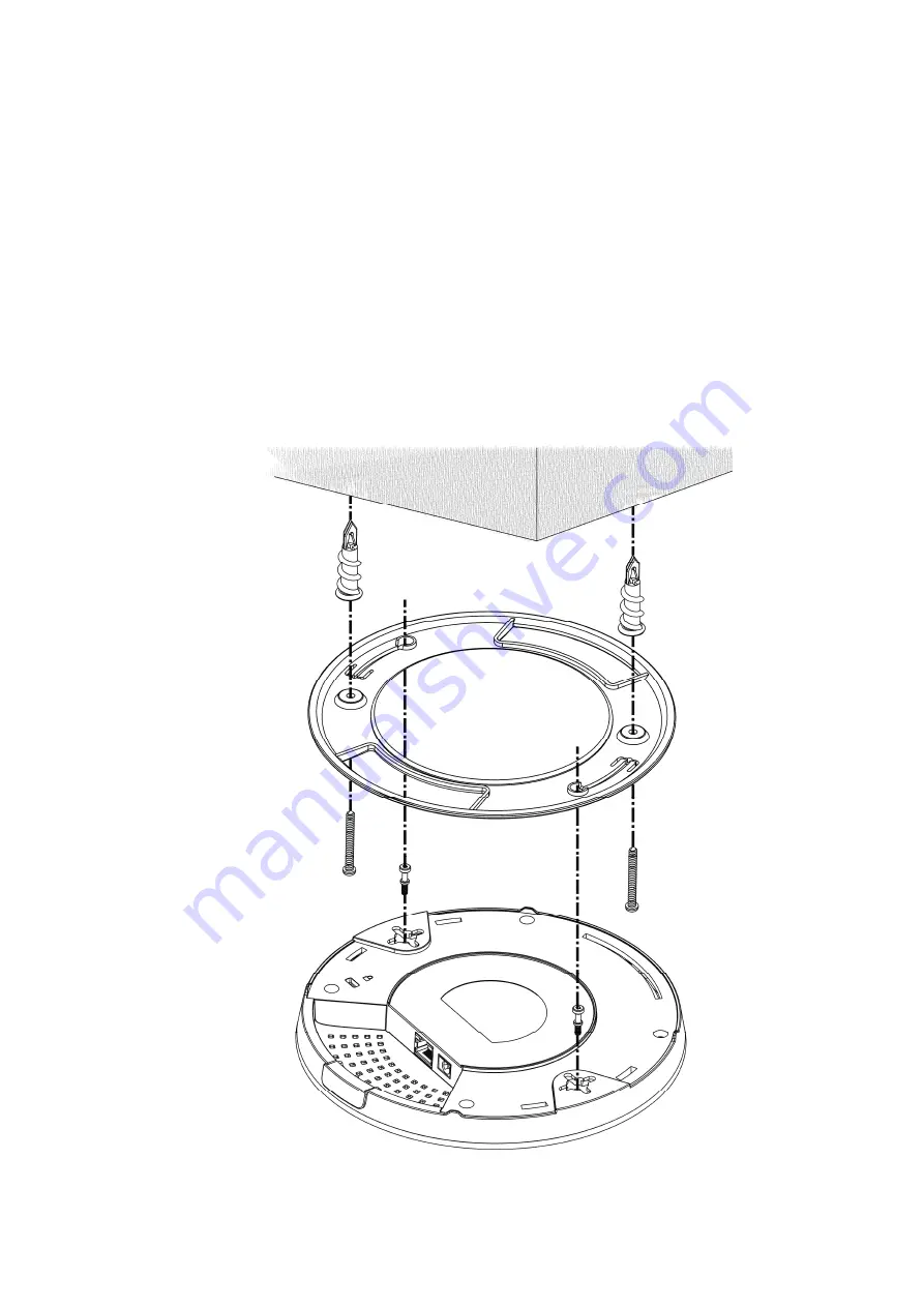
1.


Place the bracket under the plasterboard ceiling and fasten two turnbuckles 

firmly (as shown in Figure below, Step 1). 

2.


Make the screws pass through the bracket and insert into the turnbuckles (as 
shown in Figure below, Step 2). Fasten them to offer more powerful 

supporting force.   

3.


When the bracket is in place, fasten two screws firmly (as shown in Figure 
below, Step 3) on the bottom of VigorAP. 

4.


Make the device just below the bracket. Put the screws installed in Step 3 on 
the screw holes of the bracket (as shown in Figure below, Step 4). 

5.


Gently rotate the device to make screws slide into the notches of the 
bracket and move forward till it is firmly fixed. 


Bracket 

Step


1


Step 2


Step 3


Step 4


Summary of Contents for VigorAP 912C

Page 1: ...i ...

Page 2: ...ii VigorAP 912C 802 11ac Ceiling mount Access Point Quick Start Guide Version 1 1 Firmware Version V1 3 2 For future update please visit DrayTek web site Date February 27 2020 ...

Page 3: ... to prevent electronic shock hazards Keep the package out of reach of children When you want to dispose of the device please follow local regulations on conservation of the environment Warranty We warrant to the original end user purchaser that the device will be free from any defects in workmanship or materials for a period of one 1 year from the date of purchase from the dealer Please keep your ...

Page 4: ...ts are designed to provide reasonable protection against harmful interference in a residential installation This equipment generates uses and can radiate radio frequency energy and if not installed and used in accordance with the instructions may cause harmful interference to radio communications However there is no guarantee that interference will not occur in a particular installation If this eq...

Page 5: ...uncontrolled environment This equipment should be installed and operated with minimum distance 20cm between the radiator your body Operations in the 5 15 5 25GHz band are restricted to indoor usage only More update please visit www draytek com The external power supply used for each product will be model dependent 1 2 A Manufacturer DVE DVE B Address No 5 Baogao Rd Xindian Dist New Taipei City 231...

Page 6: ...eiling 4 3 3 Suspended Ceiling Lightweight Steel Frame Installation 5 3 4 Wall Mounted Installation 7 4 Connection and Configuration 8 4 1 Notifications for Hardware Connection 8 4 2 Connect to a Vigor Router using AP Management 9 4 3 Web Configurations 10 Connected As a Mesh Node in Mesh Network 10 Connected As an Access Point 10 5 Customer Service 13 Be a Registered Owner 13 Firmware Tools Updat...

Page 7: ...ling mount bracket Quick Start Guide T Rail Mounting Kits Used for suspended ceiling Fixings and Screws for ceiling mounting RJ 45 Cable Ethernet Screw set for wall mounting The type of the power adapter depends on the country that the AP will be installed UK type Power Adapter EU type Power Adapter USA Taiwan type Power Adapter AU NZ type Power Adapter The maximum power consumption is 10 Watt ...

Page 8: ... Port Connects to LAN or router Supports PoE power Gigabit 1000BaseT Power Jack DC IN Connecter for a power adapter Hole Explanation Factory Reset Restores the unit back to factory default settings To use insert a small item such as an unbent paperclip into the hole You will feel the button inside depress gently Hold it for 5 seconds The VigorAP will restart with the factory default configuration ...

Page 9: ... the bracket under the wooden ceiling and fasten two screws firmly as shown in Figure below Step 1 2 When the bracket is in place fasten two screws firmly as shown in Figure below Step 2 on the bottom of VigorAP 3 Make the device just below the bracket Put the screws installed in Step 2 on the holes of the bracket as shown in Figure below Step 3 4 Gently rotate the device to make screws slide into...

Page 10: ...into the turnbuckles as shown in Figure below Step 2 Fasten them to offer more powerful supporting force 3 When the bracket is in place fasten two screws firmly as shown in Figure below Step 3 on the bottom of VigorAP 4 Make the device just below the bracket Put the screws installed in Step 3 on the screw holes of the bracket as shown in Figure below Step 4 5 Gently rotate the device to make screw...

Page 11: ...upplied with mounts T Rail brackets which attach directly to the metal grid T Rail of your suspended ceiling 1 Choose one set of T Rail mounting kits from the bundled package 2 Put the T Rail brackets on the holes of the bottom side of the device Fasten them with suitable screws 3 If a larger gap is required between the ceiling and the VigorAP use the extension pieces to extend the height of the b...

Page 12: ...6 4 Attach the T Rail brackets to the ceiling frame Note Warning The screw set shown below is for wall mounting only Do not use such set for ceiling mounting due to the danger of falling ...

Page 13: ...ing side entry note the position of the side entry cable cutout 1 A template is provided on the VigorAP s packaging box to enable you to space the screws correctly on the wall 2 Place the template on the wall and drill the holes according to the recommended instruction 3 Fit screws into the wall using the appropriate type of wall plug as shown in the ceiling section but do not use the ceiling brac...

Page 14: ...Co on nn ne ec ct ti io on n If required remove the protective cap of VigorAP to create extra space for the cables to pass through Connect VigorAP to Vigor router via LAN port with Ethernet cable Connect VigorAP to PoE switch via LAN port with Ethernet cable For connecting with PoE switch do not connect the power adapter VigorAP will get the power from the switch directly ...

Page 15: ... and manage multiple DrayTek APs from a single interface 1 Connect one end of the power adapter to power port of VigorAP and the other side into a wall outlet 2 Access into the web user interface of Vigor router Here we take Vigor2862 as an example Open Central Management AP Status 3 Locate VigorAP 912C Click the IP address assigned by Vigor router to access into web user interface of VigorAP 912C...

Page 16: ...gorAP 912C must be configured by a remote Mesh Root e g VigorAP 903 within the mesh network The user must detect VigorAP 912C via a Mesh Root to add it as a mesh node C Co on nn ne ec ct te ed d A As s a an n A Ac cc ce es ss s P Po oi in nt t As an access point VigorAP 912C must be connected to a router and configured in AP Access Point Range Extender mode Install VigorAP on to the ceiling Use a ...

Page 17: ...f the computer to be in the same subnet as the IP address of VigorAP 912C If there is no DHCP server on the network then VigorAP 912C will have an IP address of 192 168 1 2 If there is DHCP available on the network then VigorAP 912C will receive its IP address via the DHCP server If you connect to VigorAP by wireless LAN you could try to access the web user interface through http vigorap com b Aft...

Page 18: ... the QR code named with DrayTek Wireless App to download DrayTek Wireless APP b After downloading run the APP c Click Quick Start Wizard Next scan the QR code named with Connect SSID Later click Connect to access into the APP user interface of VigorAP 912C to set the device in AP or Range Extender mode ...

Page 19: ...routers will be regularly upgraded Please consult the DrayTek web site for more information on newest firmware tools and documents http www draytek com GPL Notice This DrayTek product uses software partially or completely licensed under the terms of the GNU GENERAL PUBLIC LICENSE The author of the software does not provide any warranty A Limited Warranty is offered on DrayTek products This Limited...

Reviews: