


8
3
3
.
.
H
H
a
a
r
r
d
d
w
w
a
a
r
r
e
e
I
I
n
n
s
s
t
t
a
a
l
l
l
l
a
a
t
t
i
i
o
o
n
n
This section will guide you through installing the
router’s port conn
ections and
fitting the router securely, either to a wall using the supplied mounting hardware,
or into a 19” rack with the optional RM1 rack mounting kit.
Before starting to configure the router, you must first connect up the cables.
3
3
.
.
1
1
N
N
e
e
t
t
w
w
o
o
r
r
k
k
C
C
o
o
n
n
n
n
e
e
c
c
t
t
i
i
o
o
n
n
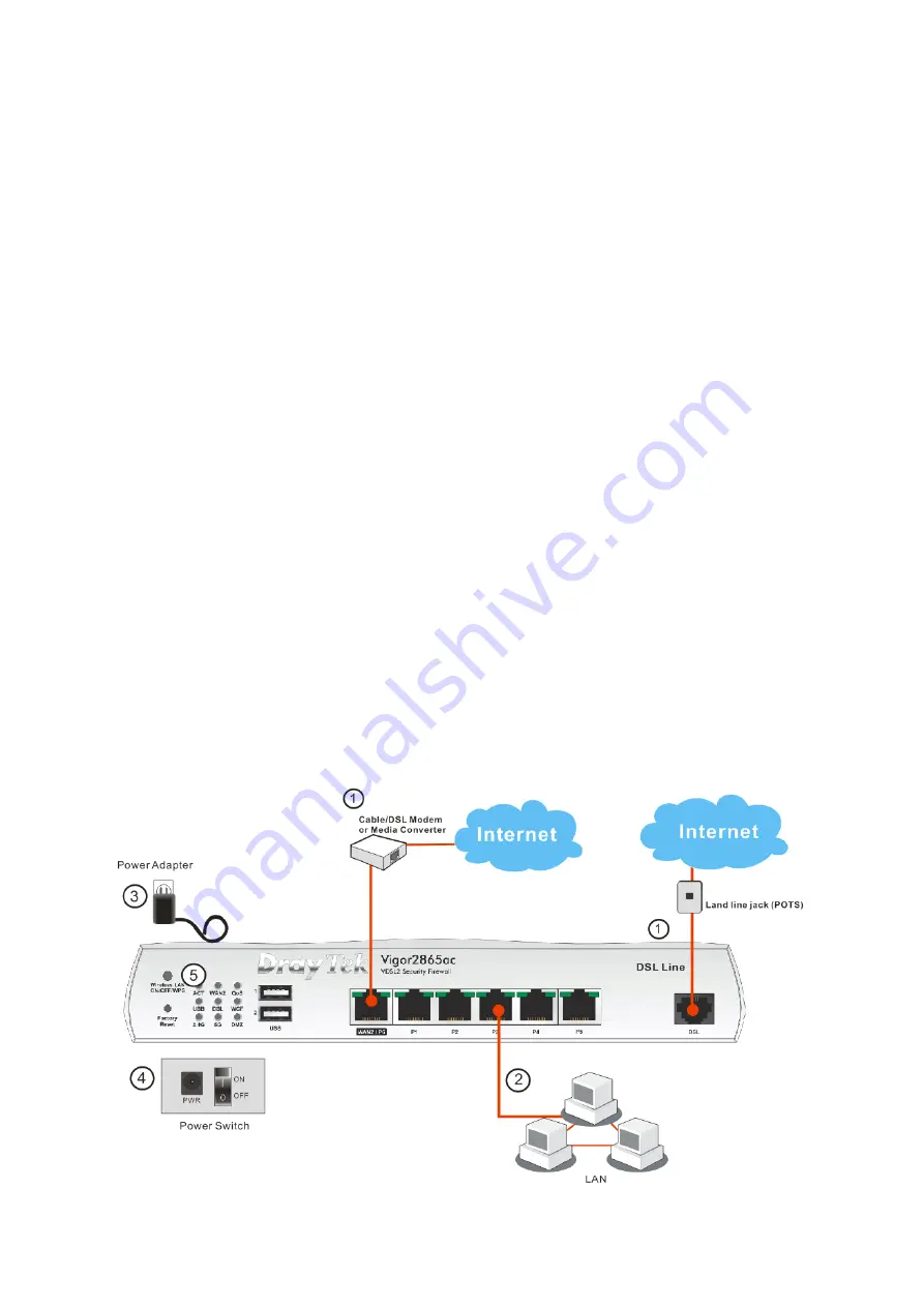
1.
ADSL/VDSL Connections:
Connect the
VDSL/ADSL
interface to the
Modem
or
DSL
port of the external splitter/microfilter (not supplied) with the
RJ-11 line cable. In some cases, your RJ-11 DSL socket will be built-into
your phone line socket on the wall and
you won’t have a separate
microfilter/splitter.
WAN2 Connections:
Connect the cable Modem/DSL Modem/Media
Converter to the WAN port of router with Ethernet cable (RJ-45).
2.
LAN Connections:
Connect a LAN port of the router to your computer or
switch.
3.
Wireless Antennas:
Screw the supplied wireless antennas on to the
antenna connectors on the back of the router.
4.
Power Supply:
Connect the power adapter to the Vigor 2865
’s PWR socket
on the rear and plug the power adapter into a suitable mains socket.
Turn the Vigor 2865 on using its power switch.
5.
The router will start up. After completing the system test, the
ACT
LED will
light up and start blinking once per second to indicate that it is ready for
use. (For more detailed information of LED status, please refer to section 3.
Panel Explanation)


