EZ-Fold Basketball Backstops by Draper—Wall-Mounted
Page 3 of 18
www.draperinc.com
(765) 987-7999
Cable Run
➀
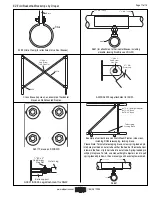
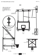
Check cable sheaves for excessive wear or looseness. Make sure
cable is still passing properly through the sheave.
➁
Inspect cable clamps for tightness; Make sure there is no slippage.
➂
Check aircraft cable for fraying. (Hint: One way to do this is by run-
ning an oily rag along the aircraft cable. The rag will snag on frays;
it will also lubricate the cable.) If fraying is encountered, contact
your dealer or Draper, Inc. for re place ment.
Caution: Wear gloves
when searching for frays.
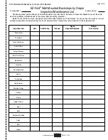
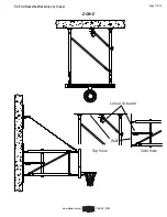
Backstop/Accessories
➀
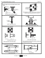
Inspect backstop legs and frame. Make sure all bolts and clamps
are tight and have not shifted. Check for cracks, corrosion, or other
signs of damage or excessive wear.
➁
Make sure Side Braces are still at proper length.
➂
Check Height Adjuster for loose clamps, or binding that keeps it
from operating correctly.
➃
Lubricate Inner Tubes of Height Adjusters with petroleum jelly.
➄
Inspect bank and goal for cracks or bending. Also make sure top of
rim is still 10' above the fl oor, and level.
➅
Check padding for tears, missing pieces, or loose sections. Re-glue
if
necessary.
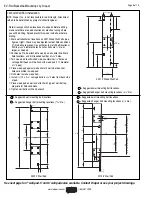
Winch Attachment/Wiring
Mounting Winch on a Flat Surface
➀
Four
9
/
16
" dia. holes are provided for mounting. Fastener type and
size required varies according to mounting surface but must be
able to safely sustain all loads imposed by the backstop.
DO NOT USE LONG EXTENSION CORDS TO POWER THE WINCH.
USE A MINIMUM OF 14/3 GAUGE MAXIMUM 100 FT WHILE
INITIALLY CON NECT ING THE WINCH DURING INSTALLATION
PERIOD. RUNNING THE WINCH UNDER BAD POWER-VOLTAGE
CONDITIONS WILL RESULT IN OVER HEAT ING AND DAMAGE TO
THE CAPACITORS.
Please Note:
Winch limit switches are pre-wired at the factory. Do not
test-run the winch with limit switches bypassed: This may cause over-
travel of the limit mechanism and result in damage to winch.
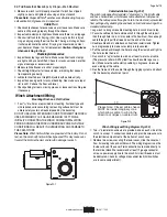
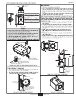
Cable Installation (see Fig. W-2)
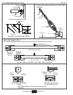
The winch is designed for standard ¼" diameter 7 x 19 aircraft cable
and has a hollow drum, which makes cable attachment simple and
reliable. The cable passes through a hole in the drum and is prevented
from pulling out by doubling the end back on itself and securing with a
standard cable clamp.
➀
Jog winch to bring wire cable mounting hole in winch drum to top.
➁
Pass wire cable end from outside winch in through the cable port,
then through hole in drum, into center of hollow drum. Pass enough
cable through to pull the free end out the end of the drum.
➂
Double cable end of cable back on itself and install clamp. Tighten
nuts progressively to make sure clamp is fully secured.
➃
Pull the cable back through the hole to snug the clamp back tight to
the hole, inside the drum.
➄
Run winch in "up" direction to wind on at least two turns of cable.
(The pressure roller will lift by itself to allow the cable to pass un-
der.) Make sure the cable starts pcablerly in its groove, to ensure
even winding of the cable.
➅
Run the free end of the cable through the rigging system and attach
it to the backstop at tach ment point.
10
'
2
'
Please
N
ote: Closest ca
b
le shea
v
e
MUST
b
e inside imaginary cone
w
hich allo
w
s ca
b
le to
w
ind in the
direction of ridges on ca
b
le dr
u
m
Figure W-2
Figure W-1
➃
Make sure winch is still properly mounted. If winch has slipped
slightly, correct and tighten bolts using an impact wrench.
Please Note:
Draper EZ-Fold
®
winches are self-lubricating. No peri-
odic application of grease or oil is required.
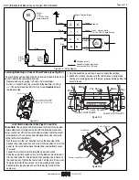
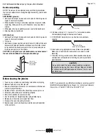
Winch Wiring (see Wiring Diagram, Fig. W-3)
➀
Two
7
/
8
" diameter knock-outs are provided, one on each side of the
winch, to accept ½" conduit connectors and provide wire access to
the electrical compartment at the bottom of winch case.
➁
Remove two screws securing the lower cover, slide the cover out
from its locating tabs and withdraw it. The wiring diagram is on the
inside surface of the cover. Field connections are made directly to
the terminal block. We recommend at least 12-gauge conductor
wire as a power supply line to the winch. All circuit breakers must
be dedicated. Check for voltage drops under load (limit switches
are in same compartment).

