EZ-Fold Basketball Backstops by Draper—Wall-Mounted
Page 2 of 18
www.draperinc.com
(765) 987-7999
Tools Needed
-Block and tackle
-
9
/
16
" and
3
/
4
" wrenches, or socket wrenches, sizes
9
/
16
" and
3
/
4
"
-Chalk line
-Plumb bob or laser plumb pointer
-Tape measure (minimum 100')
-Needle-nose pliers
-Screwdrivers (Phillips and fl at-head)
-Allen wrenches
-Impact tool
-Scaffolding and/or lift
-Carpenter’s Level
-Electric drill (
9
/
16
" and
9
/
32
" bits)
-Electric saw
-Wire cutters
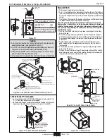
How to Use This Manual
This manual covers installation of all Draper EZ-Fold
®
wall-mounted
back stops, and is designed to be used in conjunction with project
drawings. Project draw ings show clamp num bers and positions for
each backstop. Begin at step 1, the top, and work your way down, fol-
lowing instructions for clamps provided for each specifi c installation.
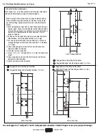
➁
Use your project draw ings, which will tell you everything from exact
locations to what clamps to use. If the drawing is to scale, the scale
can always be found at the bottom of the drawing.
➂
Dimensions are referenced from Face of Bank, Center Line of Court
or Center of Clamp. Refer to project drawings for dimensions.
Remember to account for offset dimensions (Center of Clamp to
Edge of Clamp) when marking beams for clamp placement.
➃
Prior to assembly, distribute parts to the correct backstop locations;
make sure you have the proper parts for each backstop lo ca tion.
➄
All Draper Gymnasium Equipment is supplied with Grade 5 hard-
ware. Clamps are designed to be installed with the nuts and bolts
“tight.” Draper would consider tight to be torques between 40 ft-lbs
and 60 ft-lbs.
These instructions are meant as a guide only. They do not bind
Draper, Inc. in any way and do not imply any re spon si bil i ty of Draper,
Inc. for improper installation or faulty workmanship at the jobsite.
Caution
➀
When laying out parts, be careful not to place them where
they may be in the way of scaffolding, lifts, or working areas.
➁
Before beginning assembly, locate and identify all parts using
hardware list and project drawings.
➂
Backstops must be installed level and plumb.
➃
Make sure power is disconnected before wiring winches.
➄
Do not install damaged or defective parts.
➅
For warranty information, consult separate information sheet.
➆
When calling Draper, Inc., with questions, please have your
order number, and, if possible, project drawing that was pro-
vided with your backstop.
➇
Have architect/general contractor verify backstop and
court line locations prior to beginning installation.
Installation Tips
➀
When possible, install bolts with heads toward fl oor (threads up), or
with heads toward front (threads facing rear of backstop).
Operation
➀
On wall-mounted folding models (DGW and DUW), make sure the
walls are cleared of any obstructions to proper operation.
➁
Make sure manual winches are located close to backstop, or at
least in a position that allows the operator to see the backstop be-
ing raised or lowered.
➂
Winches should be operated by qualifi ed personnel. Locate winches
where they are not easily reached, and keep manual or portable
electric operators secured when not in use.
➃
Use winches only for their original purpose; if equipment changes
are necessary, contact Draper, Inc.
➄
If you encounter a problem during installation or operation of your
backstop, contract Draper, Inc. immediately.
➅
Make sure wall is strong enough to support backstops.
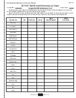
Maintenance/Inspection
NOTE: EZ-Fold
®
backstops by Draper, Inc., are designed to operate
for many years with a minimum of main te nance. However, you should
periodically inspect your wall-mounted back stops to ensure they
are in good repair and operating properly. Check backstops at least
twice a year, depending on amount of use. You will fi nd on page 7 a
maintenance checklist. Detach, make copies, and hang this list in a
convenient location to help keep track of in spec tions and repairs. If
you encounter problems, or need to replace any parts, contact your
dealer or Drap er, Inc.
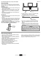
Wall/Wood Pads
➀
Check wall inside and out for cracks, crumbling mortar, or other
signs of damage.
➁
Make sure wood wall pads are not pulling away from the wall.
➂
Inspect wall pads for splits, chips, or other signs of damage or
excessive wear. Make sure they are still strongly anchored, and that
there has been no slippage.
➃
Check hardware attachments to wood wall pads. Make sure there is
no corrosion, and that all attachments are still tight.
Legs/Braces/Supports
➀
Inspect chain supports for corrosion, cracks, links pulling apart, or
other signs of damage or excessive wear.
➁
Make sure chain swivels operate smoothly, and that they have not
been bent out of shape.
➂
Check leg attachments for DGW and DUW. Make sure they are not
bent, and that the legs operate smoothly.
➃
Inspect brace and leg attachments for SW and SWD models.
Make sure they are still tightly attached, and there is no movement
up and down or side-to-side.
➄
Check telescoping cross-brace on DGW; make sure spring-loaded
locking mechanism is functioning properly.
➅
Make sure legs are still level, and that there are no cracks, dents,
or bends. Also check for cor ro sion.
Winches
➀
Examine cable drum on winch for excessive wear or looseness.
Ensure cable is wrapping correctly, and that “stacking” (cable wrap-
ping unevenly in layers) does not occur.
➁
Inspect manual winch adaptor and socket on hand or electric
operator for excessive wear (round ing of edges).
➂
Check safety lock to make sure it keeps Manual Winch Adaptor in
place.

