background image

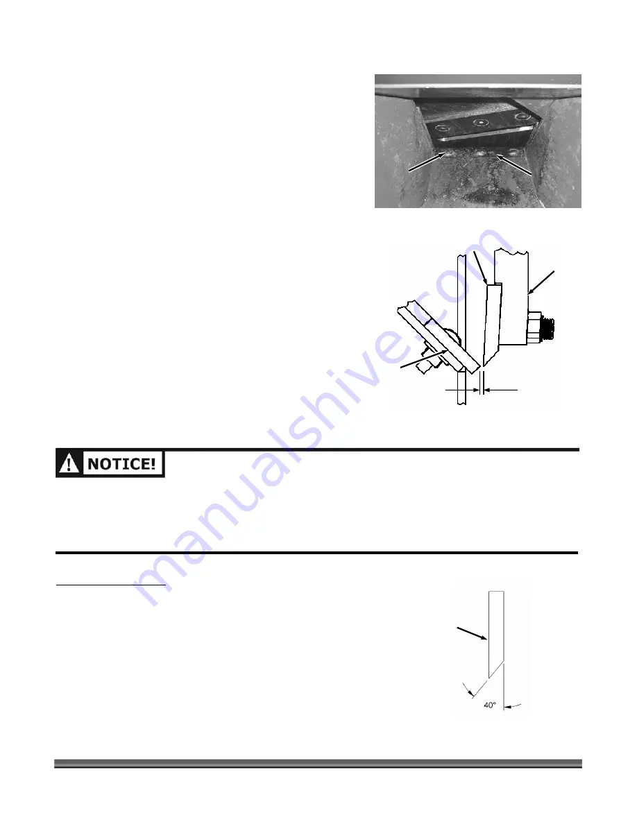
Adjusting the Knife to Wear Plate Gap 

CONTACT US AT 

www.DRpower.com

 or CALL TOLL FREE 

1-800-DR-OWNER

          39


ave a slight 

resistance.  Now you can slide the Wear Plate up or 
down (in or out) to achieve the correct gap setting 
(

Figure 40

). 

Wear Plate.  Adjust the Wear Plate against the Knife 
Gauge and tighten the Locknuts. 

3.


Check the adjustment as described in the “Che

n

the Gap” in the previous section. 

4.


Position the Chipper Hopper into t

and secure with the six Bolts, Washers an

o

5.


Re-connect the negative battery terminal wire

start only) and the spark plug wire. 

Chipper Knife Sharpening

Tools Needed: 


7/16" wrench 


Gap Gauge (provided with Chipper) 

1.


To adjust the Wear Plate Gap, loosen the three


Nuts 

on the Carriage Bolts with a 7/16" wrench just enough 
so the Wear Plate will move but still h

NOTE:

 See 

Figure 41

 for a more detailed look at the 

relationship of the Knife to Wear Plate. 

2.


Take the Gap Gauge and slide it between the Knife and 

cki g 

he Hopper Bracket 

d L cknuts. 

 (electric 


You should never attempt to sharpen the Chipper K
freehand. 


It is extremely important to consistently m
degree angle for proper performance (

Figure 42

). 


Excessive heat generated during the sharpening process 
will damage Knives and weaken the metal.  Be sure not to 
overheat the Knife during sharpening because it will 
shorten the life of the Knife. 


nife 

aintain the 40-

1/16" Gap 
(thickness of 
Gap Gauge) 

Figure 41 

Chipper 
Knife 

Wear 
Plate 

Flywheel 

AFTER ANY KNIFE OR WEAR PLATE MAINTENANCE OR ADJUSTMENT, ROTATE THE CHIPPER 
FLYWHEEL BY USING A WOODEN STICK AND WATCH AND LISTEN CAREFULLY FOR ANY UNUSUAL 
NOISES, CLICKING OR VIBRATION.  IF YOU DETECT ANY OF THESE, INSPECT THE MACHINE FOR 
DAMAGE, OR ANY LOOSE PARTS.  REPAIR OR REPLACE N

 A Y DAMAGED PARTS AND TIGHTEN ANY 

LOOSE PAR

S

TS BEFORE  TARTING THE DR RAPID-FEED CHIPPER. 

Carriage Bolt 

Wear 

and Locknut  

Figure 40 

Plate 

Figure 42 

Chipper 
Knife 

Summary of Contents for RAPID-FEED 16.50 PRO

Page 1: ...EED CHIPPER SAFETY OPERATING INSTRUCTIONS Chipper shown with Optional Accessories Serial No Order No READ AND UNDERSTAND THIS MANUAL AND ALL INSTRUCTIONS BEFORE OPERATING OR SERVICING THIS 16 50 PRO D...

Page 2: ...Representatives will be happy to help you We also hope to hear from you on how much you like your new helper In addition please tell your friends about your new 16 50 PRO DR RAPID FEED CHIPPER Having...

Page 3: ...ery Cable Electric Start 17 Adding Engine Oil and Gasoline 17 Check the Tire Pressure 19 CHAPTER 4 21 OPERATING YOUR 16 50 PRO DR RAPID FEED CHIPPER 21 Before Starting the Engine 21 Operation Notes 22...

Page 4: ...ion 52 Maintenance 52 Road Towing Package 53 Unpacking the Road Towing Package 53 Installation 54 Towing 59 Hitch Coupler Adjustment Check 60 Hitch Coupler Adjustment 60 CHAPTER 8 62 PARTS LIST AND SC...

Page 5: ...r 16 50 PRO DR RAPID FEED CHIPPER THIS INFORMATION IS IMPORTANT IN THE PROPER USE OF YOUR MACHINE FAILURE TO FOLLOW THIS INSTRUCTION COULD RESULT IN DAMAGE TO YOUR MACHINE OR PROPERTY THIS INDICATES A...

Page 6: ...Knife Tip Speed 118 mph Hopper Material 7 GA Neck 14 GA Hopper Frame Material 10 GA Steel Hopper Opening at Top 22 1 2 x 29 Machine Weight 372 Lbs manual start 392 Lbs electric start SHIPPING SPECIFI...

Page 7: ...YOU WILL BE WORKING AND REMOVE ALL FOREIGN OBJECTS LOOK FOR ROPE WIRE ETC AND REMOVE THESE OBJECTS BEFORE CHIPPING INSERTING THESE OBJECTS INTO THE CHIPPER HOPPER COULD DAMAGE THE MACHINE AND OR CAUS...

Page 8: ...241991 241811 241821 242001 127811 241831 242041 242331 electric start model only 242611 Road Towing Package only 4 16 50 PRO DR RAPID FEED CHIPPER...

Page 9: ...241841 CONTACT US AT www DRpower com or CALL TOLL FREE 1 800 DR OWNER 5...

Page 10: ...SPONSIBLE INDIVIDUALS WHO ARE FAMILIAR WITH THESE RULES OF SAFE OPERATION TO USE YOUR MACHINE NEVER PLACE YOUR HANDS FEET OR ANY PART OF YOUR BODY IN THE CHIPPER HOPPER DISCHARGE OPENING OR NEAR OR UN...

Page 11: ...HE 16 50 PRO DR RAPID FEED CHIPPER NEVER UNDER ANY CONDITIONS REMOVE BEND CUT FIT WELD OR OTHERWISE ALTER STANDARD PARTS ON THE 16 50 PRO DR RAPID FEED CHIPPER THIS INCLUDES ALL SHIELDS AND GUARDS MOD...

Page 12: ...SPARK PLUG TO PREVENT ACCIDENTAL STARTING DISCONNECT THE NEGATIVE BATTERY CABLE THEN WAIT 5 MINUTES BEFORE MAKING ADJUSTMENTS OR REPAIRS NEVER TAMPER WITH THE ENGINE S GOVERNOR SETTING THE GOVERNOR CO...

Page 13: ...DENTS OR HAZARDS OCCURRING TO OTHER PEOPLE THEIR PROPERTY AND THEMSELVES YOUR 16 50 PRO DR RAPID FEED CHIPPER IS A POWERFUL TOOL NOT A PLAYTHING EXERCISE EXTREME CAUTION AT ALL TIMES THE DESIGN OF THI...

Page 14: ...A WHILE AFTER THE ENGINE IS SHUT DOWN DISCONNECT SPARK PLUG WIRE KEEPING IT AWAY FROM THE SPARK PLUG TO PREVENT ACCIDENTAL STARTING THEN WAIT 5 MINUTES BEFORE INSPECTING FOR CLOGGING OR DAMAGE VIBRAT...

Page 15: ...or operator to maintain this equipment in compliance with state regulations is a misdemeanor under California law and may be in violation of other state and or federal regulations Contact your local...

Page 16: ...12 16 50 PRO DR RAPID FEED CHIPPER...

Page 17: ...ase feel free to contact us at www DRpower com or call our Customer Service Representatives at our toll free number 1 800 DR OWNER 376 9637 16 50 PRO DR RAPID FEED CHIPPER Controls and Features Blow B...

Page 18: ...pplies Needed Gloves Metal Shears Side Cutters Pry Bar Hammer Parts supplied on Skid Figure 2 16 50 PRO DR RAPID FEED CHIPPER Hopper Assembly Extended Top Discharge Chute if ordered see Chapter 7 Chip...

Page 19: ...if ordered Figure 5 5 Carefully cut the Steel banding holding the machine and Hopper Assembly to the pallet Figure 6 Hopper Assembly Steel Banding Chipper Assembly Plastic Banding Steel Banding 6 Cut...

Page 20: ...Nylon Lock Nuts Figure 7 NOTE Install hardware with Bolt Head on the top side Figure 7 Attaching the Discharge Chute Tools Needed Discharge Chute Figure 8 Bolts and Locknuts Tongue Assembly Hardware F...

Page 21: ...MUST ADD OIL BEFORE STARTING THE ENGINE THIS MACHINE IS SHIPPED WITHOUT OIL TRACES OF OIL MAY BE IN THE RESERVOIR FROM FACTORY TESTING BUT YOU MUST ADD OIL BEFORE STARTING THE ENGINE FILL THE RESERVOI...

Page 22: ...gure 12 Adding Gas SHUT DOWN THE ENGINE WAIT FOR ALL MOVING PARTS TO COME TO A COMPLETE STOP REMOVE SPARK PLUG WIRE DISCONNECT THE NEGATIVE BATTERY CABLE THEN WAIT 5 MINUTES BEFORE PERFORMING ANY MAIN...

Page 23: ...ools Needed Tire Pressure Gauge Air Compressor NOTE There should be 38 psi max in each tire 1 Remove the Valve Stem Protective Cap Figure 13 a check the tire pressure with a tire pressure gauge 2 If t...

Page 24: ...20 16 50 PRO DR RAPID FEED CHIPPER...

Page 25: ...E IS SHUT DOWN DISCONNECT SPARK PLUG WIRE KEEPING IT AWAY FROM THE SPARK PLUG TO PREVENT ACCIDENTAL STARTING DISCONNECT THE NEGATIVE BATTERY CABLE THEN WAIT 5 MINUTES BEFORE PROCEEDING USE ONLY A WOOD...

Page 26: ...22 16 50 PRO DR RAPID FEED CHIPPER Processing Material igned to accept wood only The Chipper Knife mounted on a revolving flywheel turns Chipper Hopper ALWAYS WEAR PROTECTIVE GOGGLES OR SAFETY GLASSES...

Page 27: ...than hardwood Your operator experience will teach you how d process them When chipping branches sometimes a tail will develop at the end of a branch To avoid this rotate the branch while feeding it i...

Page 28: ...nual Starting Chipper Ensure that the RUN CHOKE Choke Control Lever position Figure 14 Move the Choke Control Lever to the CHOKE position Figure 16 leave in the RUN position if th engine is already wa...

Page 29: ...tch to the START position until the engine starts then release it Figure 21 The Starter Switch will snap back to the ON position and the engine will continue to run 5 As the engine warms up slowly adj...

Page 30: ...move spray FLUID FILM or a similar non conductive lubricant into the keyhole NOTE Close the Fuel Shut Off Valve when transporting or storing the DR RAPID FEED CHIPPER Stopping the Engine Manual Starti...

Page 31: ...hese procedures to Adjust to the Towing tractor 1 Support the front of the Base Frame with a Jack Stand or Blocks make sure you are off to the side of the Pin Holes for Towing Position Pivot Tongue We...

Page 32: ...Remove any material left in the Chipper Ho NEVER PRY AGAINST THE SCROLL WELDMENT WHEN REMOVING THE DEFLECTOR OR DISCHARGE CHUTE OR AT ANY OTHER TIME THIS WILL CAUSE DAMAGE TO THE MACHINE 3 Remove the...

Page 33: ...sider that the service intervals shown are the maximum under normal operating conditions Increase frequencies under extremely dirty or dusty conditions Procedure Before Each Use Every 8 10 Hours Every...

Page 34: ...ws 5 Replac Grease Fitting Your RAPID FEED CHIPPER was greased at the Factory The operator needs to periodically lubricate two Bearings of the Chipper Assembly SHUT DOWN THE ENGINE WAIT FOR ALL MOVING...

Page 35: ...n the disposing of the used oil Removing Replacing and Adjusting the Drive Belt Removing and R SHUT DOWN THE ENGINE WAIT FOR ALL MOVING PARTS TO COME TO A COMPLETE STOP REMOVE SPARK PLUG WIRE DISCONNE...

Page 36: ...ng the Belt 1 Remove the eight Bolts Lock Washers and Flat Washers from the Belt Guard using a 1 2 Wrench Figures 26 and 27 2 Remove the Belt Guard 3 Remove the Locknut and Belt Guard Bracket Figure 2...

Page 37: ...e Bushing Retaining Bolt holes d Slowly tighten the Bolts evenly and alternately 1 4 to 1 2 the Bushing Saw Slot this acts as a Hub puller un Shaft e When the Sheave is loose remove the three Bolts an...

Page 38: ...ghtening the Bolts and TE Make sure that the Belt or Sheave is not r 5 Tighten olts Figure 29 on the Belt d push d tape m 7 The me re Figure 32 rement sho 9 Repeat st is achieved 10 When the Belt is p...

Page 39: ...t support the Hopper to the Chipper e the Hopper from the Chipper Assembly eed Chipper is operating at full efficiency see Regular Maintenance Checklist at the beginning of this ter Operating with a w...

Page 40: ...e Flywheel using a stick until the three countersunk Allen Screws and Lock Nuts attaching the Knife to the Flywheel are visible through the Access gs ut the heads of the Allen Screws with an Awl or rt...

Page 41: ...ten the Allen screws and Lock Nuts use the new hardware supplied with a new Knife kit to hold the Knife to the Flywheel 10 Using a 7 32 Allen wrench and a 9 16 socket tighten the center Screw and Lock...

Page 42: ...ife and Wear to check the clearance Figure 39 If the Knife Gauge slides freely with no adj e Knife Gauge will not slide down between the Knife and Wear Plate the Wear Plate must adjusted If the Knife...

Page 43: ...t the relationship of the Knife to Wear Plate 2 Take the Gap Gauge and slide it between the Knife and cki g he Hopper Bracket d L cknuts electric You should never attempt to sharpen the Chipper K free...

Page 44: ...ened to the extent that more than 3 32 is taken off this measurement Once this measurement is below 1 485 see Figure 43 Sharpened Knife or if you are unable remove dents or gouges with these guideline...

Page 45: ...ving and Replacing the Wheels The Wheels on the DR 16 50 FTP PRO Rapid Feed Chipper are pneumatic and port With use tires or Bearings may need replacing The foll ocedures 5 32 allen wrench Fine Tooth...

Page 46: ...COUL SUL LEARN TO R RLOAD CONDITION O W U CAN SUCCESSFULLY FEED MATERIA MACHINE IF INE STOP THE MACHINE IMME NE AND DO NOT STOP THE ENGINE IT CAN BURN THE D E BE COVERED UNDER WARRANTY FOR THIS REASON...

Page 47: ...to use a trickle charger Replacing th 3 Remove the Key from the keyway in the Engine Crankshaft and set it aside 4 Clean the engine crankshaft and remove any burrs and then slide the new Clutch Assemb...

Page 48: ...located near you For a fee you can recycle your batteries with the International Metals Reclamation Company Visit them at www inmetco com and click Services then click Battery Recycling or contact the...

Page 49: ...OUTDOORS ALLOW EFORE STORING IN ANY ENCLOSURE W N OULD BE STORED OUT OF THE REACH OF CHILD f Season and Storage UT DOWN THE ENGINE WAIT FOR ALL MOVING PARTS ARK PLUG WIRE DISCONNECT THE EFORE PERFORMI...

Page 50: ...46 16 50 PRO DR RAPID FEED CHIPPER...

Page 51: ...e ON position Is the spark plug wire attached Have you checked all the items under the section called Electric Starting in Chapter 4 an al for engine ic procedures Check the wire connections especiall...

Page 52: ...esh clean unleaded gas If it s old change it Use a fuel stabilizer if you keep gas longer than two weeks or so Does your engine have the right amount of clean oil If it s dirty change it following the...

Page 53: ...The machine has excessive vibration ife sharpen or replace the Knife See erly seated on the flywheel Loosen the Knife eck Check for a dull or damaged Kn Chapter 5 The Knife is not prop mounting screws...

Page 54: ...ontinued SYMPTOM POSSIBLE CAUSE The machine s wh track left or righ while being towed he machine s wh track left or righ while being towed eels t ch tire if you have the road towing option eels t ch t...

Page 55: ...outside side hest away from o Bolt nches harge Chute enables you to better control the directio harge Chute enables you to better control the directio and allows you to d and allows you to d t them i...

Page 56: ...the Discharge Ring Figure 49 2 Apply some all purpose grease in each hole of the Discharge Ring and Center Ring as you rotate the Chute 3 Rotate the Extended Top Discharge Chute for the full 180 of ro...

Page 57: ...Towing Package enables the C towed behind a vehicle that is equipped with a 2 ball hitch and transported on public roads to another site Unpacking the Road Towing Package Tools and Supplies Needed Kni...

Page 58: ...3 4 Wrenches Hitch C Bolt and ut Lockn Roa Tow Hi d Towing tch Bolt and Locknut Figure 54 Hitch Clip Pin Standard Tow Hitch and Pin Figure 55 lip Two 1 2 Wrenches 10 Adjustab Electrical Tape Jack Stan...

Page 59: ...om two holes Fender Bolt Nut Lock Washer and Flat Washer top two holes Figure 57 Bolt Nut Lock Bolt Nut and Lock Washer bottom two holes Washer and Flat Washer top two holes 5 Pull the opposite wheel...

Page 60: ...1 Slide a Taper Bearing is fa Bearing lightly Insert a Cotter Pin through the slots of the Castle Nut and into the hole in the Axle Bend the ends of the Cotter Pin with Needle nose Pliers 16 Place the...

Page 61: ...he outside of the Chipper 5 Push the Yellow Wire into the top left hole in the back of the light socket and push the Brown Wire into the top right hole Figure 65 NO ght 6 ush the Brown Wire into the t...

Page 62: ...where the wires go to either side of the Frame 7 Attach both Light Brackets to the Frame with Bolts a Locknuts with two 1 2 wrenches Figure 66 Light Bracket Figure 66 Bolt and Locknut 8 Secure the Wir...

Page 63: ...the tow 3 Slide the Locking Pin into the hole in the Latc Assembly AVOID DEATH OR SERIOUS INJURY DO NOT EXCEED 45 MPH WHEN TOWING THIS MACHINE For extra safety and security you may want to purchase a...

Page 64: ...ent procedure in the following steps Hitch Coupler Adjustment 1 With the proper size ball in the socket of the hitch coupler close the latch of the coupler completely Figure 73 Verify that the locking...

Page 65: ...CONTACT US AT www DRpower com or CALL TOLL FREE 1 800 DR OWNER 61...

Page 66: ...oove 14 242111 Bushing 1 1 4 15 24 Guard Belt 16 24213 Belt 17 242141 Cover Side Engine 2151 Bracket Guard Belt 19 241771 Bracket 3 16 20 242161 Cover Ref Part Description 21 241611 Bolt 1 4 20 X 1 24...

Page 67: ...CONTACT US AT www DRpower com or CALL TOLL FREE 1 800 DR OWNER 63 Schematic 16 50 PRO DR RAPID FEED CHIPPER...

Page 68: ...aft 1 4 SQ X 1 1 16 183221 Spacer Clutch 17 146051 Bolt 5 16 18 X 1 18 159790 Bolt 5 16 18 X 1 3 4 19 145150 Washer Flat 5 20 143130 Nut Nylon Lock 241701 Bolt Carriage 5 16 18 X 3 22 242251 Axle 3 4...

Page 69: ...Schematic 16 50 PRO DR RAPID FEED CHIPPER CONTACT US AT www DRpower com or CALL TOLL FREE 1 800 DR OWNER 65...

Page 70: ...needed 13 242441 Shim Shaft 1 1 4 050 as needed 14 242451 Shim Shaft 1 1 as needed 15 242461 Shim Shaft 1 1 4 125 as needed 16 242471 Ring Retaining 1 1 17 242481 Bolt 1 2 13 X 1 1 2 GR 5 18 Ref Part...

Page 71: ...Schematic Chipper Basic CONTACT US AT www DRpower com or CALL TOLL FREE 1 800 DR OWNER 67 CONTACT US AT www DRpower com or CALL TOLL FREE 1 800 DR OWNER 67...

Page 72: ...e 02 242521 r Weldment Left Back 5 1 4 20 Ref Part 03 242531 Hopper Weldment Right 04 242541 Hopper Top 05 242551 Shield Blow 06 242561 Support Blow Back 07 241581 Bracket Guard 08 241611 Bolt 1 4 20...

Page 73: ...Schematic Hopper Assembly CONTACT US AT www DRpower com or CALL TOLL FREE 1 800 DR OWNER 69...

Page 74: ...t 1 2 13 X 3 1 2 05 242091 Nut Nylon Lock 1 2 13 06 153890 Bolt 3 8 16 X 3 1 2 07 154480 Nut Nylon Lock 3 8 16 08 145160 Washer Flat 3 8 242611 Label Danger 45 mph 241851 Label Warning Do Not Climb OP...

Page 75: ...Schematic Accessories CONTACT US AT www DRpower com or CALL TOLL FREE 1 800 DR OWNER 71...

Page 76: ...72 16 50 PRO DR RAPID FEED CHIPPER...

Page 77: ...Notes CONTACT US AT www DRpower com or CALL TOLL FREE 1 800 DR OWNER 73...

Page 78: ...74 16 50 PRO DR RAPID FEED CHIPPER otes N...

Page 79: ...warranty period the warranty holder is responsible for the machine transportation charges if required During the warranty period warranty parts will be shipped by standard method at no charge to the...

Page 80: ...rly remove debris from the Cooling Fins A dirty Engine retains heat and can cause damage to the internal Engine parts BELT Check the Belt for wear proper alignment and tension KNIFE and WEAR PLATE Che...

Reviews: