T/MonXM Implementation
To prepare the T/MonXM WorkStation or IAM to utilize the
ASCII MUX, a port number must be defined for the MUX and
a phantom port (called a “Job”) must be defined for each of the
eight MUX ports (or less, if not all ports are currently used).
Proceed as follows:
1. Prepare all ASCII rules according to the T/MonXM man-
ual Section M6 (for regular ASCII) or M17 (for Auto-ASCII).
2. Select Remote Ports from the Parameters Menu.
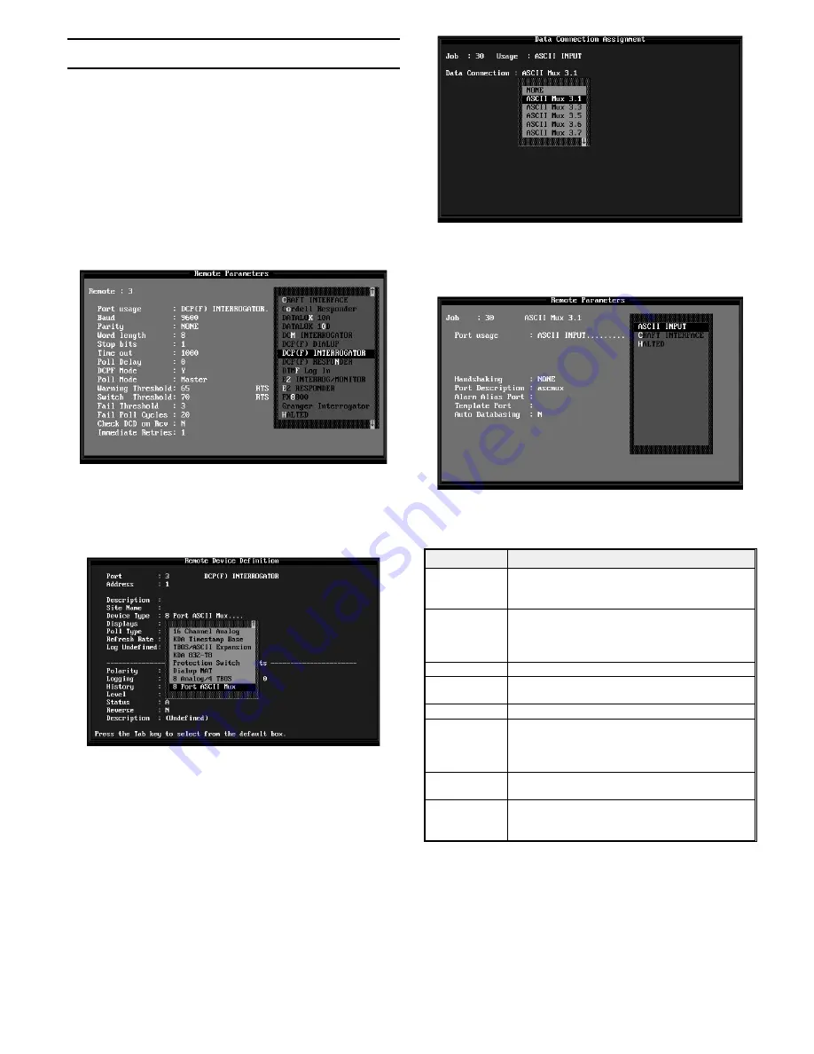
3. Select an RS232 port for the ASCII MUX. Select “DCP(F)
Interrogator” for the Port Usage field. Enter “1" in the address
field. Make appropriate entries in the other fields. (Fig. 20)
4. Press F1 to enter the Remote Device Definition screen.
Select “8 Port ASCII MUX”for the “Device Type” field. Enter
appropriate information in the rest of the fields. (See Fig. 21)
5. Do not define alarm points for this port and device.
6. Press F10 to exit the Remote Device Definition screen.
The Remote Port screen will appear. Use the “N” key to ad-
vance to “port” 30 (the screen will indicate “Job 30"). Job 30
represents one of the 8 MUX ports
7. Press F6 to define the “Data Connection.” (This defines
the MUX port to be used for this Job.) Refer to Fig. 22. From
the default box select one entry from N.1 to N.8, where N= the
defined T/MonXM port number and .1 to .8 = the MUX port
number. Only the available MUX ports will be listed. Mux
ports may be assigned in any order.
8. Press F10 to return to the Remote Parameters screen. Press
“E” to edit. Fill in the fields per Table H and Fig. 23.
Table H - Field Descriptions for the Remote Parame-
ters Screen, Job # 30 and Up
Field
Description
Job (#)
Phantom port number. Jobs 30 to 157 will be available
once a device has been defined as “8 Port ASCII
MUX.”
Port Usage
Select from default box. Default is HALTED. ASCII
INTERFACE gives port full alarm and craft interface
ability. CRAFT INTERFACE gives port craft interface
ability only.
Handshaking
Select None, Xon/Xoff or Rts/Cts. Default is None.
Port or Craft
Description
Optional 30 Character description.
Full Duplex
Y=Full Duplex. N=Half Duplex. Craft Interface only.
Alarm Alias Port Number of port whose already defined data base you
wish to use for this port. Leave blank for none. If used,
enter alias port number, then press F1 and set device
rules.
Template Port
To use a pre-defined template, enter the template num-
ber here. (801 through 803, leave blank for none.)
Auto Databasing If Auto Data-basing is being used with the device con-
nected to this MUX port, enter “Y.” If regular ASCII is
used, enter “N.”
9. Press F1 to access the Devices screen. Enter information
as for regular ASCII (T/MonXM Manual, page M6-51) or Auto
ASCII (T/MonXM Manual page M18-22).
10. Press F1 to access the Point screen. Enter information as
for regular ASCII (T/MonXM Manual, page M6-53). Point in-
formation is not applicable to Auto ASCII.
When complete, use F10 to return to the Remote Parameters
screen. Press “N” to move to the next Job # or use F10 to exit.
D-PC-180-10A-XV
7
OG109137
March 1997
Fig. 20 - Select “DCP(F) Interrogator” for the
“Port Usage” Field
Fig. 21 - Select “8 Port ASCII MUX”for the “Device
Type” Field
Fig. 22 - Select a Data Connection to Designate the
MUX Port
Fig. 23 - Fill in Remote Parameters Fields per Table H


