Dover WILDEN BioPharm T2 Series Engineering, Operation & Maintenance Download Page 4

2

WILDEN PUMP & ENGINEERING, LLC

SECTION 2

THE WILDEN PUMP — HOW IT WORKS

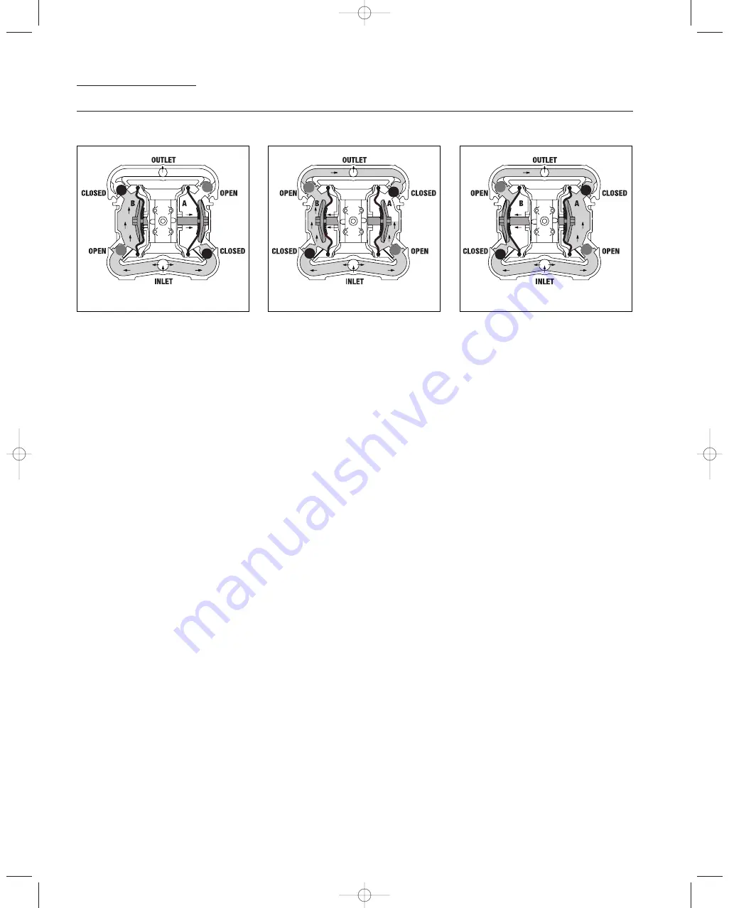
The Wilden diaphragm pump is an air-operated, positive displacement, self-priming pump. These drawings show the flow pattern
through the pump upon its initial stroke. It is assumed the pump has no fluid in it prior to its initial stroke.

FIGURE 1

The air valve directs pres-

surized air to the back side of diaphragm
A. The compressed air is applied directly
to the liquid column separated by 
elastomeric diaphragms. The diaphragm
acts as a separation membrane between
the compressed air and liquid, balancing
the load and removing mechanical stress
from the diaphragm. The compressed air
moves the diaphragm away from the
center block of the pump. The opposite
diaphragm is pulled in by the shaft
connected to the pressurized diaphragm.
Diaphragm B is on its suction stroke; air
behind the diaphragm has been forced
out to the atmosphere through the
exhaust port of the pump. The move-
ment of diaphragm B toward the center
block of the pump creates a vacuum
within chamber B. Atmospheric pressure
forces fluid into the inlet manifold forcing
the inlet valve ball off its seat. Liquid is
free to move past the inlet valve ball and
fill the liquid chamber (see shaded area).

FIGURE 2

When the pressurized

diaphragm, diaphragm A, reaches the
limit of its discharge stroke, the air valve
redirects pressurized air to the back side
of diaphragm B. The pressurized air
forces diaphragm B away from the center
block while pulling diaphragm A to the
center block. Diaphragm B is now on its
discharge stroke. Diaphragm B forces the
inlet valve ball onto its seat due to the
hydraulic forces developed in the liquid
chamber and manifold of the pump.
These same hydraulic forces lift the
discharge valve ball off its seat, while the
opposite discharge valve ball is forced
onto its seat, forcing fluid to flow through
the pump discharge. The movement of
diaphragm A toward the center block of
the pump creates a vacuum within liquid
chamber A. Atmospheric pressure forces
fluid into the inlet manifold of the pump.
The inlet valve ball is forced off its seat
allowing the fluid being pumped to fill the
liquid chamber.

FIGURE 3

At completion of the stroke,

the air valve again redirects air to the
back side of diaphragm A, which starts
diaphragm B on its exhaust stroke. As
the pump reaches its original starting
point, each diaphragm has gone through
one exhaust and one discharge stroke.
This constitutes one complete pumping
cycle. The pump may take several cycles
to completely prime depending on the
conditions of the application.

RIGHT STROKE

MID STROKE

LEFT STROKE

WIL_14070_E_01.qxd  1/4/06  6:29 AM  Page 2

Summary of Contents for WILDEN BioPharm T2 Series

Page 1: ...WIL_14070_E EOM T2M BIOPHARM 2 05 WIL_14070_E_01 qxd 1 4 06 6 29 AM Page C1...

Page 2: ...ATION AND OPERATION A Installation 6 B Operation Maintenance 7 C Troubleshooting 8 SECTION 8 DIRECTIONS FOR DISASSEMBLY REASSEMBLY A Model T2 METAL Disassembly Cleaning Inspection 9 B Turbo Flo Pump A...

Page 3: ...TY VARIES BY MODEL 900 BioPharm 901 BioPharm BSP 902 BioPharm DIN 903 BioPharm FDA Tri Clover flanges wing nuts 904 BioPharm USDA Food Master 905 BioPharm 3A CIP Wil Gard 110V 906 BioPharm 3A CIP Wil...

Page 4: ...d area FIGURE 2 When the pressurized diaphragm diaphragm A reaches the limit of its discharge stroke the air valve redirects pressurized air to the back side of diaphragm B The pressurized air forces...

Page 5: ...in the pump by turning it upside down and allowing any fluid to flow into a suitable container CAUTION Blow out air line for 10 to 20 seconds before attaching to pump to make sure all pipe line debris...

Page 6: ...0 P 8 0 3 R 32 1 3 BSP threads available DIMENSIONS T2 BIOPHARM ITEM METRIC mm STANDARD inch A 264 10 4 B 35 1 4 C 138 5 4 D 256 10 1 E 267 10 5 F 295 11 6 G 41 1 6 H 98 3 8 J 75 3 0 K 183 7 2 L 210 8...

Page 7: ...3 h 13 scfm air consumption See dot on chart Caution Do not exceed 8 6 bar 125 psig air supply pressure Flow rates indicated on chart were determined by pumping water For optimum life and performance...

Page 8: ...rime troubles will be eliminated In addition pump efficiency can be adversely affected if proper attention is not given to elevation see pump performance chart PIPING Final determination of the pump s...

Page 9: ...ecessary repairs and replacements Over a period of time such records can become a valuable tool for predicting and preventing future maintenance problems and unscheduled downtime In addition accurate...

Page 10: ...rn beyond their ability to function In this case the valve must be replaced NOTE Before the valve is scrapped it is possible that it may be saved by completely disassembling the valve cleaning all com...

Page 11: ...model T2 has a 25 mm 1 inlet and 19 mm outlet and is designed for flows up to 95 lpm 25 gpm The single piece center section consisting of center block and air chambers is molded of polypropylene or al...

Page 12: ...tched or gouged Using an adjustable wrench remove diaphragm assembly from shaft Inspect all parts for wear and replace with genuine Wilden parts if necessary Figure 9 Step 4 Figure 4 Remove the discha...

Page 13: ...working tolerances and should be replaced If the piston does not move freely in the air valve the entire air valve should be immersed in a cleaning solution NOTE Do not force the piston by inserting a...

Page 14: ...r clamp bands to the desired torque see this page for torque specs Description of Part Metal Pumps Air Valve 3 4 N m 30 in lbs Outer Piston 38 0 N m 28 ft lbs Vertical Bolts 13 0 N m 115 in lbs MAXIMU...

Page 15: ...13 WILDEN PUMP ENGINEERING LLC NOTES WIL_14070_E_01 qxd 1 4 06 6 29 AM Page 13...

Page 16: ...14 WILDEN PUMP ENGINEERING LLC SECTION 9A EXPLODED VIEW PARTS LISTING T2 METAL AIR OPERATED TEFLON FITTED WIL_14070_E_01 qxd 1 4 06 6 29 AM Page 14...

Page 17: ...02 6802 08 14 Pistons Inner 2 02 3750 01 02 3750 01 02 3750 01 02 3750 01 02 3750 01 15 Pistons Outer 2 02 4600 03 02 4600 04 02 4600 03 02 4600 03 02 4600 04 16 Stud Bolt 2 02 6150 08 02 6150 08 02...

Page 18: ...ro Seal 37 Turcite 48 Expanded PTFE 49 Polyurethane 50 Polyurethane ester 51 Neoprene 52 Buna N Nitrile 53 Viton FKM 54 Nordel EPDM 55 Teflon PTFE 56 Saniflex Hytrel 57 FDA Wil Flex 58 Wil Flex 59 Tef...

Page 19: ...WIL_14070_E_01 qxd 1 4 06 6 29 AM Page BC1...

Page 20: ...WIL_14070_E_01 qxd 1 4 06 6 29 AM Page BC2...

Reviews: