


14
OM-DH(T) DOMESTIC & (CE) INTERNATIONAL
2. Replace with new pressure gauge ensuring that an adequate sealing
compound is used.
3. Once the pressure gauge has been replaced, the kettle jacket will require
venting.
OM-SM-DH-CE
17
OM/SM-DH-CE
Recommended spacings are shown in this drawing.
DH-20 shown
g) Ensure that there is an adequate spark at
the sparking electrode and that the burners
light smoothly and without delay.
h) As the burners ignite, ensure that the
sparking sequence stops and that the
burners remain lit.
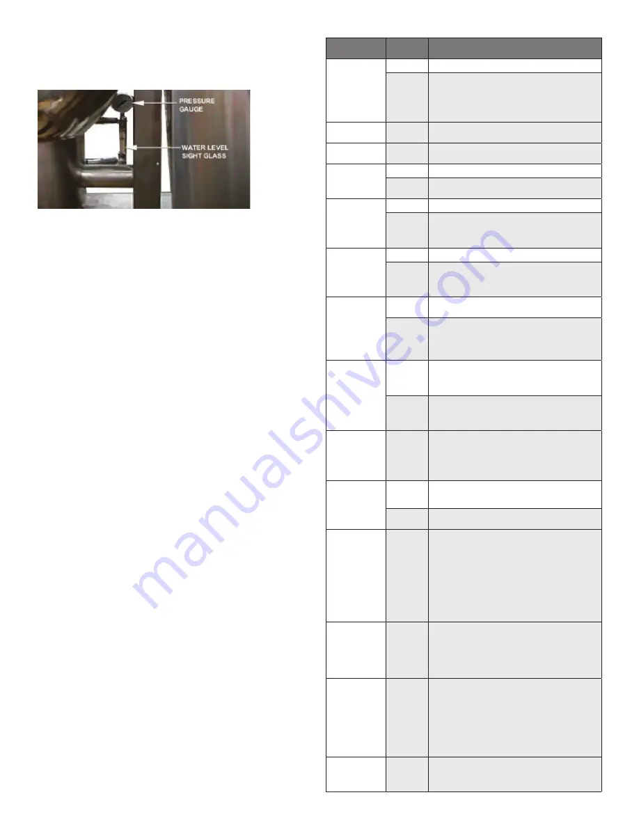
3.17
Removal of Pressure Gauge (Turn the
gas and electricity mains off)
a) Using the correctly sized spanner remove
the pressure gauge from top of the sight
glass.
b) Replace with new pressure gauge ensuring
that an adequate sealing compound is used.
c) Once the pressure gauge has been
replaced, the kettle jacket will require
venting. (Para 3.2)
3.18
Removal of Sight Glass (Turn the gas
and electricity mains off)
a) Remove sight glass protection bars.
b) Undo top and bottom compression fittings.
c) Allow the water in the sight glass to drain.
d) Remove the sight glass.
e) Replace in reverse order.
15 mm
13 mm
REMOVAL OF SIGHT GLASS (TURN THE GAS & ELECTRICITY MAINS OFF)
1. Remove sight glass protection bars.
2. Undo top and bottom compression fittings.
3. Allow the water in the sight glass to drain.
4. Remove the sight glass.
5. Replace in reverse order.
6. Once the sight glass has been replaced, the lost jacket water requires
replacement.
REMOVAL OF STEAM SAFETY VALVE (TURN THE GAS & ELECTRICITY MAINS OFF)
1. Remove the elbow from the safety valve.
2. Remove the steam safety valve from kettle jacket pipework.
3. Replace in reverse order.
4. Ensure an adequate sealing compound is used to seal the safety valve.
5. Once the steam safety valve has been replaced the jacket will need to be
vented. See detailed Instructions pertaining to Steam Safety Valve installation
and operation.
REMOVAL OF FILLING VALVE (TURN THE GAS & ELECTRICITY MAINS OFF)
1. Remove filling valve from kettle jacket pipework.
2. Replace in reverse order.
3. Ensure adequate sealing compound is used to seal the valve.
4. Once the fill valve has been replaced the jacket will need to be vented.
REPLACEMENT PARTS
To order parts, contact your Authorized Service Agent. Supply the model
designation, serial number, part description, part number, quantity, and when
applicable, voltage and phase.
CONTACT US
If you have questions pertaining to the content in this manual, contact Unified
Brands at 888-994-7636.
TROUBLESHOOTING
This unit is designed to operate smoothly and efficiently if properly maintained.
However, the following is a list of checks to make in the event of a problem.
Wiring diagrams are found at the end of this manual. When in doubt, turn unit
off and call for service at 888-994-7636. If an item on the check list is marked
with (X), it means that the work should be done by an Authorized Service Agent.
SYMPTOM
WHO
WHAT TO CHECK
X indicates items which must be performed by authorized technician.
Display not lit
(Advanced only)
User
a. That power supply is on.
Auth Service
Rep Only
b. Fuses, accessible by removing caps on the side of the control box.
c. For loose or broken wires. X
d. Temperature controller functioning, by listening for a click
when the switch opens or closes and verifying LEDs on back
of board. X
e. Contactor functioning. X
PROB in display
(Advanced only)
Auth Service
Rep Only
a. For loose or broken wires or damaged/failed RTD probe. X
b. PCB board malfunction/failure
HI in display
(Advanced only)
Auth Service
Rep Only
a. For loose or broken wires or damaged/failed RTD probe. X
b. PCB board malfunction/failure
Kettle is hard to tilt
User
a. Gears for foreign materials, and lubrication.
Auth Service
Rep Only
b. Gears for alignment. X
c. Worm gears or broken gears. X
Kettle continues
heating
after it reaches the
desired temperature
User
a. Temperature Controller dial setting.
Auth Service
Rep Only
b. Temperature Controller calibration and offset.X
c. Temperature Controller operation. The Temperature Controller
should click when the dial is rotated to settings above and
below the temperature of the kettle.X
Kettle stops heating
before it reaches the
desired temperature
User
a. Temperature Controller dial setting.
Auth Service
Rep Only
b. Temperature Controller calibration and offset.X
c. Temperature Controller operation. The Temperature Controller
should click when the dial is rotated to settings above and
below the temperature of the kettle.X
Safety Valve pops
open
User
a. For air in the jacket. See “Jacket Vacuum” in the Maintenance
b. Temperature Controller dial setting.
Auth Service
Rep Only
c. For defective Temperature Controller. The relay should click
when the dial is rotated to settings above and below the
temperature of the kettle. If defective, replace.X
d. For defective safety valve. If the valve pops at pressures below
49 PSI, replace.X
Burners will not light
User
a. That the main gas supply valve is open. (handle is in line with
gas pipe).
b. Gas supply to the building.
c. That the kettle body is not tilted.
Auth Service
Rep Only
d. Temperature Controller operation. The relay should click
when the dial is rotated to settings above and below the
temperature of the kettle.X
e. That tilt limit switch is closed when body is not tilted.X
System does not
produce a
spark
Auth Service
Rep Only
a. AC voltage between terminals on secondary side of
transformer. If it is not 24 Volt, replace the transformer. X
b. That the high tension cable is firmly attached and in good
condition. If cracked or brittle, replace.X
c. Pilot electric ceramic for crack or break.X
d. Pilot spark gap. Regap.X
Safety valve leaks
a small amount of
steam when kettle
is operating
User
a. For contamination that prevents seating of the valve. With full
pressure in the jacket, pull the leer all the way briefly to blow
the valve clean, then let the lever snap back to seat the valve
Auth Service
Rep Only
b. Safety valve for defects. Replace any defective valve with an
identical valve. X
Spark is present
but the pilot will
not light
Auth Service
Rep Only
a. That the pilot valve is securely connected to terminals. X
b. For 24 VAC at terminals PV and PV/MV. If 24V is not present,
replace the ignition control module. X
b. That gas pressure is at least 3.5” W.C. (8.7818 ub).
c. For gas at the pilot. If it is not flowing:
(1) Check the pilot gas line for kinks and obstructions. X
(2) Clean orifice, if necessary. X
(3) Check magnetic operator for pilot valve on gas valve.
Repair or replace as necessary. X
d. That the pilot spark gap is located in the pilot gas stream. If
not, adjust or replace the pilot burner. X
e. For drafts. Shield the pilot burner, if necessary. X
Pilot lights, but
main burner will
not come on and
spark does not
stay on
Auth Service
Rep Only
a. For 24 V between terminals MV and PV/MV while pilot is burning.
If 24V is not present, replace the ignition control module. X
b. That gas pressure is at least 3.5” W.C.(8.7818 ub). X
c. Electrical connections of the main valve to terminals, to
assure that they are securely attached. Check magnetic
operator for main valve on gas valve. Repair or replace
as necessary. X
Pilot lights, but
main burner will
not come on, the
spark stays on
Auth Service
Rep Only
a. Check for bad burner ground. If necessary, repair with
high temperature wire. X
b. Pilot burner ceramic insulator for cracks. X
c. That cable is not grounded out. If it is, correct the
ground-out condition or replace cable. X
d. For proper gas pressure. X
e. Clean pilot assembly, or replace if necessary. X
f. Tighten all mechanical and electrical connections. X
g. If the pilot flame is weak, increase pilot orifice size. X
h. Replace ignition control module. X
Main burner
comes on but will
not stay on
Auth Service
Rep Only
a. Check burner ground for bad wire or connection. Replace
if necessary with high temperature wire. X
b. Check for low gas supply pressure. If necessary, replace
ignition control module. X
Summary of Contents for unified brands groen DH-20
Page 16: ...16 OM DH T DOMESTIC CE INTERNATIONAL Parts List GAS VALVE PIPING BOTTOM COMPONENTS ...
Page 27: ...27 OM DH T DOMESTIC CE INTERNATIONAL Wiring Diagram Domestic For Classic Control Models ...
Page 28: ...28 OM DH T DOMESTIC CE INTERNATIONAL Wiring Diagram Domestic For Advanced Control Models ...
Page 29: ...29 OM DH T DOMESTIC CE INTERNATIONAL Wiring Diagram CE ...