


10
OM-DH(T) DOMESTIC & (CE) INTERNATIONAL
SERVICING & CONVERSION
IMPORTANT: BEFORE ATTEMPTING ANY SERVICING, ENSURE THAT THE ISOLATING
COCK IS TURNED OFF AND CANNOT BE INADVERTENTLY TURNED ON.
ENSURE ALSO THAT THE ELECTRICITY SUPPLY IS DISCONNECTED. AFTER
ANY MAINTENANCE TASK, CHECK THE APPLIANCE TO ENSURE THAT IT
PERFORMS CORRECTLY AND CARRY OUT ANY NECESSARY ADJUSTMENTS
AS DETAILED IN THIS MANUAL. ALWAYS CHECK FOR GAS SOUNDNESS
AFTER CARRYING OUT ANY SERVICING OR EXCHANGE OF GAS CARRYING
COMPONENTS.
NOTE:
1. WHEN REPLACING WIRING CONNECTIONS REFER TO THE WIRING
DIAGRAM CONTAINED ON THE UNIT AND WITHIN THIS MANUAL.
2. WHEN ANY THREADED GAS CONNECTION IS DISTURBED FOR ANY
REASON, THE THREADS MUST BE RESEALED WITH APPROPRIATE GAS
LEAK PREVENTION SEALANT THAT IS SUITABLE FOR THE TYPE OF GAS.
UNIFIED BRANDS/GROEN RECOMMENDS GAS SEALANT COMPOUND SUCH
AS LOCKTITE® 243 OR UNIFIED BRANDS PART NUMBER 122002.
WARNING: AVOID ANY EXPOSURE TO THE STEAM BLOWING OUT OF THE SAFETY
VALVE.
CAUTION: BEFORE TESTING, MAKE CERTAIN DISCHARGE PIPE IS PROPERLY
CONNECTED TO VALVE OUTLET AND ARRANGED TO CONTAIN AND SAFELY
DISPOSE OF BOILER DISCHARGE (SEE “INSTALLATION INSTRUCTIONS”).
AFTER SERVICING
1. Test for gas soundness as specified in IGE/UP1 as appropriate after any gas
connection has been disturbed.
2. If leaks are found, disconnect the mating parts, clean the threads and apply
recommended sealant as specified in Note 2 above.
WARNING
Do not leave
any wood splinter or bristles from brush in the burner or injector. Fire could
result.
3. Check for correct operation, as appropriate (see commissioning of
appliance).
REGULAR SERVICING PROCEDURES
The following must be serviced at regular intervals.
BURNERS
The burner should be cleaned periodically to maintain maximum performance.
Burners are best cleaned with a wire brush and any blocked parts are best
cleaned with a metal broach, taking care not to damage the burner head. The
injector orifice should be cleaned with a wooden splinter. Metal reamers may
distort or increase the orifice size and should be avoided. WARNING - Do not
leave any wood splinter or bristles from brush in the burner or injector. Fire
could result.
GEARS
The gear housing has fitting for proper lubrication of moving parts. The gears
do not run in oil, periodic lubrication with grease is necessary. Frequency of
lubrication will depend on operating conditions, but it should be performed at
least once every 6 months. It is recommended that a #2 grade LGI lithium grease
be used. Add grease through the Zerk fittings on the gear housing until grease
flows out of bearings around the trunnion shaft. Place a liberal amount of grease
on the gear to cover the arc that is in contact with the worm gear.
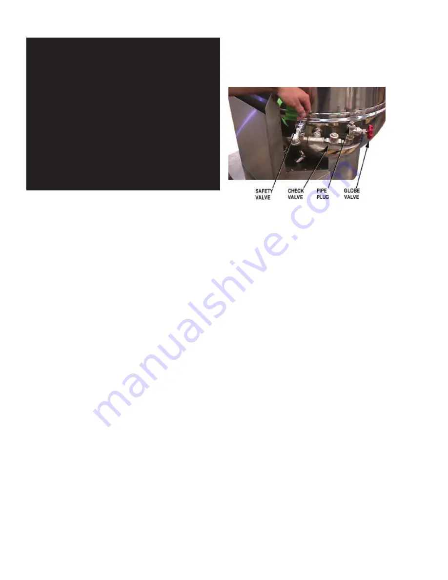
SAFETY VALVE (STEAM)
At least twice a month the safety valve requires checking to make sure it works
correctly. When the gauge pressure is about five PSI, lift the valve lever enough
to vent steam, then quickly let it snap back into place. This procedure should
be explained to the user, since it is to be carried out at least twice a month.
Safety procedures and requirements should also be explained to the user when
carrying out the procedure.
SAFETY VALVE OPERATING INSTRUCTIONS
If adding water to the boiling pan jacket, DO NOT ALLOW water to flow through
safety valve as sediment or debris may be deposited on seating surface. To
achieve topmost performance and maximum service life, it is necessary to
maintain a proper pressure margin between set pressure of the safety valve and
equipment operating pressure.
The minimum required pressure margin for this type of valve is 10% of the safety
relief valve set pressure, but not less than five PSI. UNDER NO CIRCUMSTANCES
SHOULD THIS MARGIN BE LESS THAN 5 PSI. Failure to maintain this operating
margin may result in water leakage past the seat and accumulation of deposits
on the seating surface. Excessive deposits may prevent the valve from operating
properly, and a dangerous pressure build-up and equipment rupture may result.
MAINTENANCE AND TESTING
OM-SM-DH-CE
11
OM/SM-DH-CE
Test the operation of the safety valve on a
regular basis.
The minimum required pressure margin for this
type of valve is 10% of the safety relief valve set
pressure, but not less than five PSI.
UNDER NO
CIRCUMSTANCES SHOULD THIS MARGIN
BE LESS THAN 5 PSI. Failure to maintain this
operating margin may result in water leakage
past the seat and accumulation of deposits on
the seating surface. Excessive deposits may
prevent the valve from operating properly, and a
dangerous pressure build-up and equipment
rupture may result.
Maintenance and Testing
CAUTION
BEFORE TESTING, MAKE CERTAIN
DISCHARGE PIPE IS PROPERLY
CONNECTED TO VALVE OUTLET AND
ARRANGED TO CONTAIN AND SAFELY
DISPOSE OF BOILER DISCHARGE (SEE
“INSTALLATION INSTRUCTIONS”).
Under normal operating conditions a “try lever
test” must be performed every two months.
Under severe service conditions, or if corrosion
and/or deposits are noticed within the valve
body, testing must be performed more often. A
“try lever test” must also be performed at the end
of any non-service period.
Test at or near maximum operating pressure by
holding the test lever fully open for at least 5
seconds to flush the valve seat free of sediment
and debris. Then release lever and permit the
valve to snap shut.
If lift lever does not activate, or there is no
evidence of discharge, discontinue use of
equipment immediately and contact a licensed
contractor or qualified service personnel.
Neither Conbraco Industries, Inc. nor its agents
assume any liability for valves improperly
installed or maintained.
This quality Conbraco safety relief valve, along
with proper installation, use, and maintenance,
will provide many years of reliable service and
protection against excessive pressure build-up of
water/steam. Use of this valve for any other
purpose or media places all responsibility upon
the user. Before installing valve or operating
equipment to which it is installed, read
instructions carefully. Always wear proper safety
equipment.
INSTALLATION OF SAFETY VALVE (STEAM)
a) Installation must be performed by qualified
service personnel only.
b) The BTU/hr or lb/hr rating of this valve must
equal or exceed that of the equipment to
which it is attached.
c)
DO NOT use this valve on a coal or wood
boiler having an uncontrolled heat input.
d) Ensure that all connections, including the
valve inlet, are clean and free from any
foreign material.
e) Use pipe compound sparingly, or tape, on
external threads only.
f)
DO NOT USE A PIPE WRENCH! Use
proper type and size wrench on wrench pads
only.
g) This valve must be mounted in a vertical,
upright position directly to a clean, tapped
opening in the top of the boiler or equipment.
Under no circumstances should there be a
flow restriction or valve of any type between
the safety relief valve and the pressure
vessel
h)
WARNING! During operation, this valve
may discharge large amounts of steam
and/or hot water. To reduce the potential for
bodily injury and property damage, a
discharge line
MUST be installed that:
Test the operation of the safety valve on a regular basis.
Under normal operating conditions a “try lever test” must be performed every
two months. Under severe service conditions, or if corrosion and/or deposits are
noticed within the valve body, testing must be performed more often. A “try lever
test” must also be performed at the end of any non-service period.
Test at or near maximum operating pressure by holding the test lever fully open
for at least 5 seconds to flush the valve seat free of sediment and debris. Then
release lever and permit the valve to snap shut.
If lift lever does not activate, or there is no evidence of discharge, discontinue
use of equipment immediately and contact a licensed contractor or qualified
service personnel.
Neither Conbraco Industries, Inc. nor its agents assume any liability for valves
improperly installed or maintained.
This quality Conbraco safety relief valve, along with proper installation, use,
and maintenance, will provide many years of reliable service and protection
against excessive pressure build-up of water/steam. Use of this valve for any
other purpose or media places all responsibility upon the user. Before installing
valve or operating equipment to which it is installed, read instructions carefully.
Always wear proper safety equipment.
I
NSTALLATION OF SAFETY VALVE (STEAM)
1. Installation must be performed by qualified service personnel only.
2. The BTU/hr or lb/hr rating of this valve must equal or exceed that of the
equipment to which it is attached.
3.
DO NOT
use this valve on a coal or wood boiler having an uncontrolled heat
input.
4. Ensure that all connections, including the valve inlet, are clean and free from
any foreign material.
5. Use pipe compound sparingly, or tape, on external threads only.
6.
DO NOT USE A PIPE WRENCH!
Use proper type and size wrench on wrench
pads only.
7. This valve must be mounted in a vertical, upright position directly to
a clean, tapped opening in the top of the boiler or equipment. Under no
circumstances should there be a low restriction or valve of any type between
the safety relief valve and the pressure vessel
8.
WARNING
! During operation, this valve may discharge large amounts of
steam and/or hot water. To reduce the potential for bodily injury and property
damage, a discharge line MUST be installed that:
Summary of Contents for unified brands groen DH-20
Page 16: ...16 OM DH T DOMESTIC CE INTERNATIONAL Parts List GAS VALVE PIPING BOTTOM COMPONENTS ...
Page 27: ...27 OM DH T DOMESTIC CE INTERNATIONAL Wiring Diagram Domestic For Classic Control Models ...
Page 28: ...28 OM DH T DOMESTIC CE INTERNATIONAL Wiring Diagram Domestic For Advanced Control Models ...
Page 29: ...29 OM DH T DOMESTIC CE INTERNATIONAL Wiring Diagram CE ...