OM-NHFP
OM-NHFP
5
Inspection and Unpacking
The unit will arrive completely assembled,
wrapped in protective plastic on a heavy skid, in
a heavy cardboard carton. Immediately upon
receipt, inspect the carton for damage. Report
any apparent shipping damage or an incorrect
shipment to the delivery agent.
When installation is to begin, get someone to
assist in removing the carton. Lift it straight up
and away from the unit.
Do not simply raise it
and push backwards - you will break the
cover assembly vent handle.
Write down the
model number, serial number, and installation
date of your unit, and keep this information for
future reference. Space for these entries is
provided at the top of the Service Log in this
manual.
Cut the straps holding the unit on the skid, and
lift the unit straight up off the skid.
CAUTION
SHIPPING STRAPS ARE UNDER TENSION
AND CAN SNAP BACK WHEN CUT.
UNIT WEIGHS 500 TO 660 LB (230 TO 255
KG). FOR SAFE HANDLING, INSTALLER
SHOULD OBTAIN HELP AS NEEDED, OR
EMPLOY APPROPRIATE MATERIALS
HANDLING EQUIPMENT (SUCH AS A
FORKLIFT, DOLLY, OR PALLET JACKET)
TO REMOVE THE UNIT FROM THE SKID
AND MOVE IT TO THE PLACE OF
INSTALLATION.
Installation
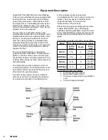
The NHFP or NHFP(E) Braising Pan should be
installed in a ventilated room for efficient
performance. Items which might obstruct or
restrict the flow of air for combustion and
ventilation must be removed. The area directly
around the braising pan must be cleared of all
combustible material.
WARNING
INSTALLATION OF THE BRAISING PAN
MUST BE DONE BY PERSONNEL
QUALIFIED TO WORK WITH GAS AND
ELECTRICITY. IMPROPER INSTALLATION
CAN RESULT IN INJURY TO PERSONNEL
AND/OR DAMAGE TO EQUIPMENT.
1. Installation on combustible floors is
allowed, with a minimum clearance to
combustible and noncombustible
construction of six inches at the rear,
two inches at the left, and zero inches at
the right.
2. Install the unit under a vent hood.
3. Level the unit by adjusting the bullet feet
or floor flanges on the legs. Make sure
the tilting mechanism has been run all
the way to the horizontal position. Check
levelness with a spirit level set on the
bottom of the pan body. Anchor the rear
legs securely to the floor.
4.
Complete the piping to the gas service
by using 1/2 inch IPS pipe or approved
equivalent.
WARNING:
THIS UNIT IS FOR COMMERCIAL USE.
NEVER USE HOME OR RESIDENTIAL
GRADE GAS CONNECTIONS. THEY DO
NOT MEET GAS CODES AND COULD BE
HAZARDOUS.
5. For a unit on casters, complete
connection to the gas supply with
connectors that comply with the
standard for Connectors for Moveable
Gas Appliances, ANSI Z21.69a-latest
edition. Restrain movement of the unit
by attaching a cable or chain to the
eyelet (provided at the back of the
frame) and anchoring the cable or chain
to the wall or floor. Make the length and
location of the cable such that the unit
cannot pull on the gas connection while
the cable is connected. The gas
connection must be made with a quick
disconnect device which complies with
ANSI Z21.41b - latest edition.


