background image

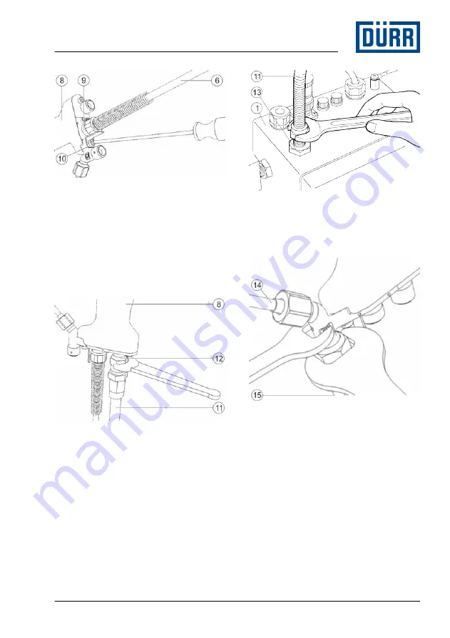
Fig. 5: Connect connection cable

5. Bolt connection cable (6) to the input (9) 

of the spray gun (8).

6. To prevent it from becoming loose, fasten 

connection cable (6) using the fastening 

bracket (10). Make sure that the cap nut 

of the connection cable (6) is positioned 

on the fastening bracket (10) with a flat 

side.

Fig. 6: Connect compressed air hose

7. Screw on compressed air hose (11) to the 

compressed air connection (12) of the 

spray gun (8).

Fig. 7: Connect compressed air hose

8. Screw on compressed air hose (11) to the 

“AIR OUT” connection (13) of the electro-

static controller (1).

Fig. 8: Connecting material supply

9. Connect material supply (15) to the paint 

pipe (14).

Assembly

11/2019

EcoGun AS MAN EC - MSG00022EN

9/52

Summary of Contents for EcoGun AS MAN EC

Page 1: ...EcoGun AS MAN EC Manual Spray Gun with External Charging MSG00022EN V03 N36180001V www durr com Operation manual...

Page 2: ...tions and specifications of every kind Illustrations can deviate from the tech nical construction Validity range of the document This document describes the following product N36180001V EcoGun AS MAN...

Page 3: ...nce 20 8 1 Safety notes 20 8 2 Maintenance schedule 21 9 Faults 21 9 1 Safety recommendations 21 9 2 Defects table 22 9 3 Troubleshooting 25 9 3 1 Replace needle nozzle and seal kit 25 9 3 2 Replace f...

Page 4: ...nd external charging sup port the coating process The spray gun is hand held The following factors influence the spray jet and therefore the result Alignment of the air cap 6 5 Alignment of the air ca...

Page 5: ...mples of wrong use are Aiming the spray gun at humans or ani mals Use outside of an spray booth Use without mechanical ventilation Atomization of fluid nitrogen Use of unapproved materials Combination...

Page 6: ...e system in which the product is installed from compressed air and material supply Depressurize the lines Secure the system against being switched on again Noise The noise during normal operation may...

Page 7: ...for completeness and integrity Report defects immediately Hotline and Contact 3 2 Handling of packaging material ENVIRONMENT Incorrect disposal Incorrectly disposed packaging material can damage envi...

Page 8: ...ipment Protective workwear Anti Static Safety Boots 1 WARNING Sources of ignition may cause explo sions Ensure a non explosive atmosphere Fig 2 Connect compressed air supply 2 Bolt compressed air supp...

Page 9: ...sitioned on the fastening bracket 10 with a flat side Fig 6 Connect compressed air hose 7 Screw on compressed air hose 11 to the compressed air connection 12 of the spray gun 8 Fig 7 Connect compresse...

Page 10: ...ely every 5cm Do not glue plastic tape and metal ties around the connection cable 5 Commissioning Ground spray gun and surroundings Ground spray gun and the surroundings to ensure safe operation and g...

Page 11: ...Ground material supply system 2 Ground material supply system Fig 12 Ground operator 3 Ground operator Fig 13 Ground work piece 4 Ground the work piece Commissioning 11 2019 EcoGun AS MAN EC MSG00022E...

Page 12: ...tion cable the compressed air hose and the material supply were assembled 4 2 Connecting Fig 14 Open ball valve 1 Open ball valve 1 Fig 15 Switch on electrostatic controller 2 Switch on the electrosta...

Page 13: ...m components of the product Chemical reactions can cause explosions Serious injuries and death can be the consequence Only use rinsing agents and cleaning agents that do not contain any halo genated h...

Page 14: ...attern width 230 350mm Flow rate 230 400mL min 6 4 Changing the air cap Personnel Operator additional qualification high tension technology additional qualification explosion pro tection Protective eq...

Page 15: ...gun Personnel Operator additional qualification high tension technology additional qualification explosion pro tection Protective equipment Anti Static Safety Boots Protective workwear Eye protection...

Page 16: ...material compo nents get damaged Use only the rinsing agents that are compatible with the components and the material Refer to safety data sheet of material manufacturer 6 7 2 Rinsing spray gun NOTIC...

Page 17: ...out any material residue Collect detergent in the collecting tray 7 Ensure proper disposal of the exiting material and rinsing agent 8 Depressurize detergent supply 9 Disconnect detergent supply 7 Cle...

Page 18: ...Do not use abrasive cleaning tools Do not poke blocked nozzles with met allic objects Do not use compressed air for cleaning Do not use any thinner spray guns Do not use high pressure for cleaning age...

Page 19: ...nal qualification high tension technology additional qualification explosion pro tection Protective equipment Protective workwear Protective gloves Anti Static Safety Boots For a thorough cleaning air...

Page 20: ...le replace ment parts in explosive areas Replacement parts not compliant with the explosion protection specifications can cause explosions in an explosive atmos phere Serious injuries and death can be...

Page 21: ...harges Before carrying out any work Switch off electrostatic controller Discharge electrode by means of a grounding rod In this pull the trigger completely Verify no current is present WARNING Risk of...

Page 22: ...al spray pattern problems Spray pattern Fault identification Spray jet is distorted Spray jet is bent or tapered Spray jet is too thick in the middle Spray jet is split Spray jet is uneven Faults 11 2...

Page 23: ...e and seal kit Spray jet is too thick in the middle Material too viscous Change material consistency Horn air pressure too low Decrease the horn air pressure via the flat jet control Air pressure too...

Page 24: ...sity is too low Increase viscosity Paint leakage on the nozzle Nozzle 27 is soiled or defective Replace nozzle 9 3 1 Replace needle nozzle and seal kit Electrode needle 26 is defective Replace electro...

Page 25: ...switch Applicable documents oper ating instructions of the controller Warning tone or alarm on the controller Basic housing 24 conta minated with paint Clean basic housing 7 2 Cleaning Paint hose con...

Page 26: ...Remove air cap 4 4 Pull the trigger 11 completely The needle is pulled backwards so that it will not be damaged during dis assembly of the nozzle 5 5 Unscrew and remove the nozzle 5 with the supplied...

Page 27: ...Disassemble needle 15 Remove needle 12 and compression spring 13 Assembly 16 Insert compression spring 13 and needle 12 in the housing 17 Move trigger 11 over the housing until the bores are one over...

Page 28: ...Static Safety Boots Requirements The spray gun is disassembled 10 2 Disassembly Disassembly Fig 32 Disassemble valve 1 Open valve 1 2 Unscrew and remove the valve 1 with the supplied open end wrench...

Page 29: ...ty Boots Requirements The spray gun is disassembled 10 2 Disassembly Disassembly Fig 34 Disassemble adjusting screw 1 Unscrew and remove the adjusting screw 1 with the supplied open end wrench include...

Page 30: ...ic Safety Boots Disassembly Fig 36 Replace handle 1 Loosen screws 3 using a hexagon socket wrench 2 Remove connecting piece 2 3 Disconnect cable 1 Fig 37 Replace O rings of the handle 4 Replace O ring...

Page 31: ...valve set 1 4 Insert compression spring 2 5 Assemble material flow control 9 3 3 Replace material flow control 9 3 6 Replace hook Personnel Operator additional qualification high tension technology a...

Page 32: ...d seal kit Disassembly Fig 40 Disassemble cover 1 Remove cover 1 Fig 41 Assemble sealing ring 2 Remove sealing ring 2 Assembly 3 Insert sealing ring 2 4 Fit cover 1 5 Press against the cover 1 such as...

Page 33: ...The spray gun is disassembled 10 2 Disassembly Disassembly Fig 42 Disassemble cover 1 Loosen cover 1 with open end wrench SW22 Fig 43 Loosen nuts 2 Loosen the nuts 2 4 with the supplied open end wren...

Page 34: ...sen the nut 2 with the supplied open end wrench included in the tool kit 2 Loosen three screws 1 Fig 46 Disconnect cascade connection 3 Carefully pull housing 6 and basic housing 3 apart 4 Disconnect...

Page 35: ...1 by hand by 90 and pull it off Fig 49 Replace O ring 2 Replace O ring 2 Assembly 3 Insert electrode 1 by hand up to the stop Turn into spraying direction until a clicking sound is heard 10 Disassemb...

Page 36: ...6 7 Rinsing 2 Switch off electrostatic controller 3 Disconnect the compressed air supply and material feed Secure against recon nection 4 Disconnect all lines 5 Clean spray gun 7 Cleaning 10 3 Disposa...

Page 37: ...ed on the housing and features the following details Product name Material number Year of manufacture Serial number CSA logo CSA information Manufacturer 11 6 Materials used Component Material Connect...

Page 38: ...12 Replacement parts tools and accessories 12 1 Replacement parts Fig 51 Exploded view Replacement parts tools and accessories 11 2019 EcoGun AS MAN EC MSG00022EN 38 52...

Page 39: ...3 Collar bushing 2 M05020112 4 Hook 1 M19060021 5 Hex screw 1 M41010030 6 Adjusting screw color 1 M41040155 7 Valve 1 M54990029 8 Trigger 1 M69040007 9 Pipe set straight 1 N36960222 Fig 52 Exploded v...

Page 40: ...ring 1 M68010285 17 Valve set air 1 N36960226 18 Sealing ring 1 M08010561 19 Housing set 1 N36960213 20 Handle set 1 N36960216 21 Electrode set 1 N36960208 22 Cover 1 M59012347 23 Sealing ring 1 M0801...

Page 41: ...ation Quan tity Material number 29 Hex screw 2 M41010033 Fig 54 Replacement parts basic housing Basic housing Item Denomination Quan tity Material number 30 Hex screw 1 M41010033 Replacement parts too...

Page 42: ...tion Quan tity Material number 31 O Ring 1 M08030958 Fig 56 Replacement parts cascade Cascade Item Denomination Quan tity Material number 32 O Ring 2 M08030956 33 Spring 1 M68010291 Replacement parts...

Page 43: ...tity Material number 34 O Ring 1 M08030952 Fig 58 Replacement parts adjusting screw color Adjusting screw color Item Denomination Quan tity Material number 35 O Ring 1 M08030954 Replacement parts tool...

Page 44: ...Denomination Quan tity Material number 36 O Ring 1 M08030959 Fig 60 Replacement parts cap nut Cap nut Item Denomination Quan tity Material number 37 Sealing ring 1 M08010562 Replacement parts tools an...

Page 45: ...ion Quan tity Material number 38 Hex screw 2 M41010033 39 O Ring 1 M08030953 40 O Ring 1 M08030955 41 Hex screw 2 M41010034 42 Stop 1 M47060304 43 Handle end A 1 N36960232 Replacement parts tools and...

Page 46: ...0116 45 Connection 1 M01010241 46 Cover 1 M59012350 47 Pipe straight 1 M34010667 48 Plug sleeve 1 M20050004 49 Nut 1 M30180068 Air cap overview Air cap type Item Material number HN400 M35030249 HN600...

Page 47: ...020037 12 3 Accessories Denomination Material number Extension cable plug connection 10m E09070247 Extension cable plug connection 20m E09070248 Cleaning set 21 parts N36960038 Maintenance kit EcoGun...

Page 48: ...from unsuitable replace ment parts in explosive areas Replacement parts not compliant with the explosion protection specifications can cause explosions in an explosive atmos phere Serious injuries and...

Page 49: ...air connect 8 Connect 8 Connections Air connection 37 Material connection 37 Contact 2 D Defects Table 22 Dimensions 36 Disassembly 36 Discharge energy 37 Disposal 36 Handling packaging material 7 E...

Page 50: ...iew 4 Short description 4 Protective equipment 7 Electrostatic discharge 7 Purge 16 Q Qualification 6 Qualification of the personnel 6 R Replacement Cascade 34 Electrode 35 Flat jet control 28 Handle...

Page 51: ...Storage 7 T Technical data Material specification 37 Operating conditions 37 Technical Data Connections 37 Tools Tool kit 47 Training 7 Type plate 37 V Valve set replacement 31 W Weight 36 Work area 8...

Page 52: ...Germany www durr com Phone 49 7142 78 0 The reproduction and distribution of this document use and communication of its contents are not permitted without express written approval Offenders will be li...

Reviews: