background image


44 

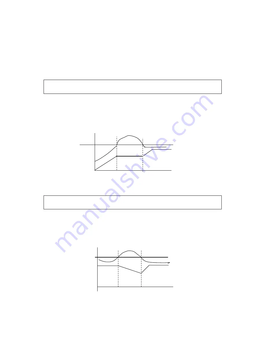
When the inverter is in decelerating, due to the effect of load inertia, the motor will produce a 

return energy to the inverter and cause the DC voltage of the inverter to increase. So when the function 

of overvoltage stall prevention is set valid and the DC voltage of the inverter becomes too high, the 

inverter will stop decelerating till the DC side voltage decreases to its rated value, then the inverter 

will go on to execute deceleration and the deceleration time will be extended automatically. 

*  Note:    When  the  output  voltage  is  higher  the  inverter  will  become  abnormal  or  turn  to 

protection. In such case P079 can be set to 0 (Invalid), which is easy to cause overvoltage protection. 


P080        Stall Prevention Level during Acceleration       

Set Range:    0~200%                        Unit:    1%                      Factory Setting:    150 

        When the inverter is in accelerating, due to over load or too short acceleration time, the output 

current of the inverter will go up quickly and exceed the rated standard level. When this happens, the 

inverter will stop accelerating until the current returns under its rated value, will the inverter go on to 

accelerate. When using the frequency track function the value of P080 should be lowered properly. 

The  greater the load initia quantity  is, the smaller the  value of  P080  should  be set. Otherwise  it  is 

extremely easy to cause overcurrent protection. 

                                          I 

      Stall Prev. Level 

                                                                                                                      Output frequency 


                                                                                                    T 

100% current is the rated current of the motor. When this parameter is set to 0, the stall prevention 

function is invalid. 


P081        Stall Prevention Level at Constant Speed       

Set Range:    0~200%                              Unit:    1                        Factory Setting:    0 


When the inverter is in constant running, due to load fuctuation and other reasons, the current 

will  go  up. When  the  current  exceeds  its  rated  value,  the  inverter  will  lower  the  output  frequency. 

When  the  output  current  returns  to  its  normal  range  the  inverter  will  accelerate  again  to  its  set 

frequency. 


Stall prevention level 

during running 


                                                                                                          Output frequency 


                                                                                                              T 

100% current is the rated current of the motor. When this parameter is set to 0, the stall prevention 

function is invalid. 


Summary of Contents for DLM1-01D5S2G

Page 1: ...soned by specialized personnels The marks of and other symbols in the manual remind you of the safety precautions during the handling installation running and inspection Please follow these instructions to make sure the safe use of the inverter In case of any doubt please contact our local agent for consultation Our professional persons are willing and ready to serve you The manual is subject to c...

Page 2: ...inal of the inverter Never remodel or replace control boards and components by yourself It may expose you to an electrical shock or explosion etc Caution Do not make any voltage withstanding test with any component inside the inverter These semi conductor parts are subject to the damage of high voltage Never connect the AC main circuit power supply to the output terminals U V W of the inverter The...

Page 3: ... 1 Main Circuit Wiring Schematic Diagram 13 3 2 Descriptions of Terminal Blocks 14 3 3 Basic Connection Diagram 15 3 4 Precautions on Wiring 16 3 5 Optional parts 18 Ⅳ Maintenance and Troubleshooting 19 4 1 Maintenance check Notes 19 4 2 Regular inspection program 19 4 3 Fault information and troubleshooting 20 Ⅴ Instruction of the Digital Operator 23 5 1 Description of the Digital Operator 23 5 2...

Page 4: ...rong with the innerparts wiring and circuit board Check if each terminal is tightly locked and if there is any foreign article inside the inverter Check if the operator buttons are all right 1 2 Before Power up Caution Check to be sure that the voltage of the main circuit AC power supply matches the input voltage of the inverter E terminals are grounding terminals Be sure to make correct grounding...

Page 5: ... install the inverter in a space with explosive gas to avoid the risk of explosion If the inverter is used at or above 1000m above seal level the cooling effciency will be reduced so please run it by de rating Do not install any switch component like air circuit breaker or contactor at the output of the inverter If any of such components must be installed because of the requirements of process and...

Page 6: ...on STOP F05 0 FWD RUN light and Fans operation 1 5 During Operation Danger Never connect or disconnect the motor set while the inverter is in running Otherwise it will cause over current trip and even burn up the main circuit of the inverter Never remove the front cover of the inverter while the inverter is powered up to avoid any injury of electric shock Do not come close to the machine when the ...

Page 7: ... higher speed Do not check the signals on circuit boards while the inverter is running to avoid danger Be careful when changing the inverter settings The inverter has been adjusted and set before ex work Do not adjust it wantonly Please make proper adjustments according to the required functions Do consider the vibration noise and the speed limit of the motor bearings and the mechanical devices wh...

Page 8: ... 660V 690V Plant code 1 2 3 6 5 4 1 Inverter series 2 Plant code 3 Inverter capacity Mark Specification Mark Specification Mark Specification DLM M series 1 General purpose 0D40 400W DLB B series 0D75 750W DLH H series 01D5 1 5KW 02D2 2 2KW 4 Power phase 5 Rated input voltage 6 Inverter type Mark Specification Mark Specification Mark Specification S Single phase 2 220V G General purpose T Three ph...

Page 9: ...munication RS 485 Operation Temperature 10 40 Humidity 0 95 Relative Humidity without dew Vibration Below 0 5G Frequency Control Range 0 10 600 00Hz Accuracy Digital 0 01 10 40 Analog 0 1 25 10 Set Resolution Digital 0 01Hz Analog 1 of Max Operating Frequency Output Resolution 0 01Hz Operator Setting Method Press directly to set or use potentiometer Analog Setting Method External Voltage 0 5V 0 10...

Page 10: ...se function drawing control auto energy savings etc Protection Functions Overload Protection Electronic relay protection motor Drive 150 1 min for constant torque 120 1min for fans pumps FUSE Protection FUSE activates and motor stops Over voltage DC Voltage 400V for 220V class DC Voltage 800V for 380V class Under Voltage DC Voltage 200V for 220V class DC Voltage 400V for 380V class Instant Stop an...

Page 11: ...will lead to the deterioration of electrolytic capacity If it needs to be stored for a long time make sure to power it up one time within a year and the power up time should be at least above five hours When powered up the voltage must be increased slowly with a voltage regulator to the rated voltage value 2 5 Installation Site and Environment The inverter should be installed at the following loca...

Page 12: ...e inverter please put a flat board under the inverter bottom base and install it again If the inverter is installed on a loose surface stress may cause damage of parts in the main circuit so as to damage the inverter The inverter should be installed on non combustible materials such as iron plate If several inverters are installed upper and lower together in one cabinet please add heat dissipation...

Page 13: ... Use one of anti high harmonic Electromagnetic contactor Note Do not use the electromagnetic contactor as the on off button of power supply for the inverter AC reactor It is recommended to install an AC reactor for power factor improvement if the input capacity is more than 1000KVA Inverter Be sure to make correct connections of the main circuit wires and control signal wires of the inverter Be su...

Page 14: ...C reactor E Ground terminal 4 Function Description of Control Circuit Terminals Symbol Function Description Default setting FWD Multi Digital Input 1 Forward REV Multi Digital Input 2 Reverse RST Multi Digital Input 3 Reset SPH Multi Digital Input 4 High speed SPM Multi Digital Input 5 Medium speed SPL Multi Digital Input 6 Low speed GND Common Ground 10 Power Supply for Analog Setting 10V VI Mult...

Page 15: ...nclosure The terminals must be connected correctly as the following wiring circuit diagrams The following diagram shows the Default setting standard connection of Model DLM1 FWD Inverter R S T Single Three Phase 220V GND DRV W V U E VI REV SPH SPM SPL RST GND 10V GND E AI Ground terminal FC FA FB Power input Multi Digital Output Relay 3A 250VAC 3A 30V DC M 24V 100mA AM GND Analog output RS 485 Com...

Page 16: ...the inverter or add a reactor at the inverter Please lower the carrier frequency when there is a longer distance between the inverter and the motor Because the higher the carrier frequency is the bigger the leakage current of high order harmonics in the cables will be The leakage current will have unfavorable effect on the inverter and other equipment Specifcations of Non Fuse Breaker and Wire Mod...

Page 17: ...nding wire should be kept away from the power supply wires for large power equipment The grounding method for several inverters together should be done as the frst and second diagrams below Avoid the third a Good b Good c Not Good ...

Page 18: ...the high capacity models When using the GFCI sometimes our malfunction can lead to protection circuit So when you use of GFCI should pay attention to the GFCI selection while appropriate to reduce the carrier frequency shorten lead and so on 2 Braking resistor Model Braking resistor s Metering Brake torque 10 ED Special motor KW W Ω DLM1 0D40S2G 80 200 125 0 4 DLM1 0D75S2G 100 200 125 0 75 DLM1 01...

Page 19: ...ke sure the voltage of supply power conforms to the required voltage of inverter Especially attention to the power cable and the motor if there is damaged Please check wiring terminals and connectors if there are loose Please make sure power line terminals are not off shares Please pay attention to dust inside the inverter iron and corrosive liquids Please do not measure the insulation resistance ...

Page 20: ...t and output line insulation 2 Check whether the motor jis jammed or mechanical load is abruptly changed 3 The capacity of inverter is too small please increase the capacity 4 Please check if the grid voltage is abruptly changed Deceleration Overcurrent Stop Overcurrent 1 Please check the motor for short circuit and output line insulation 2 Increase the deceleration time 3 The capacity of inverter...

Page 21: ... check the mechanical load if there is stuck 3 Reset the V F curve Motor overload 150 1 minute 1 Please check the mechanical load if there is a sudden change 2 The motor doesn t match with the inverter 3 Motor thermal insulation deterioration 4 Voltage fluctuations 5 Please make sure if there is a missing phase 6 Mechanical load increases Motor Over torque 1 Please check the mechanical load if the...

Page 22: ...gency Stop Emergency Stop status 20 4 20mAz Connect break Pr Parameter setting error Set parameter correctly DCb DC braking DC braking status E XX Y Code Table A B C D E F G H O S N L T P R U 2 Fettle Alarm information Fault S Stop Y A Accelerate N Constant D Deceleration ...

Page 23: ...rrent AC V DC V Forward reverse temperature etc Run key Function key Value change key Stop Reset key Potentiometer 5 2 Description of Indicator Lamp Status 1 Description of Indicator Lamp Status Indicator lamp Status Description FWD on The motor is in forward rotation REV on The motor is in reverse rotation RUN on Run STOP on Stop 2 Description of Display Items No Display Meaning 1 Present output ...

Page 24: ...rature counter PID feedback value and the speed can only be displayed after setting specific parameter 2 When under FWD REV PXXX and parameter content state after a few seconds the display can be automatically restored to the frequency voltage current etc interface 3 When in running and stopping status original interface is still shown but the corresponding content will vary depending on the opera...

Page 25: ...ion frequency P001 Acceleration Time Set Range 0 1 6500 0 Unit 0 1s Factory Setting 5 0 P002 Deceleration Time Set Range 0 1 6500 0S Unit 0 1s Factory Setting 5 0 Accelerat ing Time means the time needed for the inverter frequency from 0Hz to 50Hz Decelerating Time means time needed for inverter frequency from maximum frequency to 0Hz DLM1 Series inverters have 4 Accel Decel Times For Accel Decel ...

Page 26: ...26 ...

Page 27: ... cause motor over current or under torque or even an inverter tripping P007 set value is limited by P005 P008 Min Voltage Set Range 0 1 50 0V Unit 0 1V Factory Setting undefined This parameter can set the lowest starting voltage in the V F curve This setting value is limited by the voltage at the highest operating frequency P009 Min Frequency Set Range 0 1 20 00 Hz Unit 0 01Hz Factory Setting This...

Page 28: ...nge 0 1 Unit 1 Factory Setting 0 Two starting modes are available for different equipment 0 Start from the starting frequency When P092 is set as 0 i e DC brake is invalid at start it starts running from its starting frequency When P092 is set to any non zero value i e DC brake is valid when starting it will first have a DC braking at start and then start from the starting frequency Refer to P091 ...

Page 29: ...ed This function is suitable when the motor cannot have reverse rotation and to prevent workers from false operation When the reverse rotation is forbidden the motor can only rotate forward and cannot have reverse rotation When the reverse rotation is forbidden if switching between For Rev rotation on the panel the panel will show Rev Run but the motor is actually making forward rotation with the ...

Page 30: ...her but the heating capacity will be small So the carrier frequency should be set as low as possible especially with large power machines if the noice demand is not so high P020 Starting Frequency Set Range 0 1 10 0 Hz Unit 0 1Hz Factory Setting 0 5 Starting frequency is the initial frequency when the inverter is started If the starting frequency is set to 4 0Hz the inverter will begin to run at 4...

Page 31: ...N OFF OFF Multi speed 1 set by P035 OFF ON OFF Multi speed 2 set by P036 ON ON OFF Multi speed 3 set by P0375 OFF OFF ON Multi speed 4 set by P038 ON OFF ON Multi speed 5 set by P039 OFF ON ON Multi speed 6 set by P040 ON ON ON Multi speed 7 set by P041 Note 1 To realize excternal 8 speed control it is only valid when Multi input is set for Multi speed 1 2 3 and P024 is set to 2 2 Multi speed 1 2 ...

Page 32: ...he running status of frequency will not be memorized 4 Internal Multi speed control F P042 P043 P044 P045 P046 P047 P048 P049 T Note 1 Main speed and 7 speeds compose 8 speeds 2 Acel Decel Time of each speed is set by PLC Acel Decel Time P027 and P028 3 Running Time is set by Timer P042 P049 Set timer to 0 if not used 4 Running direction of each speed is determined by P026 5 Restart after power of...

Page 33: ... sequence with the speeds and times set by each internal parameter for infinite loops During the loop run except the commands of stop external faults and emergency stop all other commands will not be accepted F P036 P037 P040 P000 P041 P038 P039 P035 T P042 P043 P044 P045 P046 P047 P048 P049 2 Stop after the program runs automatically for one cycle stop at intermediate intervals beween different s...

Page 34: ...alue for the setting of this parameter For instance bit 0 7 7 6 5 4 3 2 1 0 0 1 0 0 1 0 1 0 0 For 1 Rev Main Speed P000 For Step 1 P035 Rev Step 2 P036 For Step 3 P037 Rev Step 4 P038 For Step 5 P039 For Step 6 P040 Rev Step 7 P041 For The parameter value 01001010 is converted to a decimal value 1 26 1 23 1 21 64 8 2 74 Then P026 74 P027 PLC Accel Decel Time 1 Set Range 0 65535 Unit 1s Factory Set...

Page 35: ...33 Accel Time 4 Set Range 0 1 6500S Unit 0 1S Factory Setting 100 0 P034 Decel Time 4 Set Range 0 1 6500S Unit 0 1S Factory Setting 100 0 P035 Frequency 2 Factory Setting 15 0 P036 Frequency 3 Factory Setting 20 0 P037 Frequency 4 Factory Setting 25 0 P038 Frequency 5 Factory Setting 30 0 P039 Frequency 6 Factory Setting 35 0 P040 Frequency 7 Factory Setting 40 0 P041 Frequency 8 Factory Setting 0...

Page 36: ...ntrolled Timer 2 start 17 High Speed High middle and low speed can compose three kinds of different operation patterns 18 Middle Speed In the three terminals the high end signal has priority 19 Low Speed Determined by Frequency 3 4 20 Multi speed 1 Multi speed 1 2 3 can compose 7 Steps 21 Multi speed 2 22 Multi speed 3 23 Acel Decel Select 1 This terminal can be used to selcect the acel decel time...

Page 37: ...nd SPM should be Accel Decel Time 1 2 Select SPH Terminal SPM Terminal Result OFF OFF Accel Decel Time 1 ON OFF Accel Decel Time 2 OFF ON Accel Decel Time 3 ON ON Accel Decel Time 4 D Function description of High middle and low terminals F H S M S L S M F RUN COMMAND L S M S FWD REV RST GND STOP RUN P012 1 P050 02 P051 03 P052 04 When triggering FWD the inverter will rotate forward starting When t...

Page 38: ...tor is delected for the source of the running frequency i e P013 0 When UP is closed the inverter s frequency will increment When DOWN is closed the inverter s frequency will decrement When both UP and DOWNare closed at the same time the frequency will neither increase nor decrease It is regaded as invalid When the frequency reaches the max operation frequency it will not increase When the frequen...

Page 39: ...ault indication The contact will act when the inverter detects abnormal condition 03 Zero Speed The contact will act when the output frequency is lower than starting frequency 04 DC Braking indication The contact will act when the inverter is in DC braking condition 05 Set Frequency reach The contact will act when the output frequency reaches the set frequency 06 Random Frequency 1 Reach The conta...

Page 40: ...ctromagnetic Relay act When the contact pulls in the corresponding multi function terminal will act 32 Braking Resistor act When the inverter in running and the DC voltage reaches the braking voltage the contact will act P058 Multi output AM Set Range 0 7 Unit 1 Factory Setting 0 Function In combination with P059 it can be connected to a frequency meter with the measuring range of 0 10V for extern...

Page 41: ...ill reset During running if the machine stops due to fault the timer will count time normally and not suspend if the machine stops due to power off the timer will reset automatically P064 Counter Set Range 0 9999 Unit 1 Factory Setting 0 An external terminal of multi function can be used as a trigger for the counter When the counter reaches set value P064 the corresponding multi function output co...

Page 42: ...ximum Analog Quantity Current Quantity For example When 10V and 20mA are respectively entered the output frequency of the inverter is 50Hz In case the max operation frequency is set to 50Hz P073 Analog Low End Frequency Set Range 0 0 600 0Hz Unit 0 1Hz Factory Setting 0 0 P074 Bias Direction of Low End Frequency Set Range 0 1 Factory Setting 0 0 Forward dirction 1 Reverse direction P075 Analog Hig...

Page 43: ...higher the value of P078 is set the slower the responding speed of analog commands Too low setting of P078 may cause the instability of frequency with fluctuation P079 Overvoltage Stall Prevention Set Range 0 1 Unit 1 Factory Setting 1 0 Overvoltage stall prevention function is invalid 1 Overvoltage stall prevention function is valid Setting P073 50 P074 1 P075 50 P076 0 P077 1 0 50Hz P073 50 P074...

Page 44: ...ceed the rated standard level When this happens the inverter will stop accelerating until the current returns under its rated value will the inverter go on to accelerate When using the frequency track function the value of P080 should be lowered properly The greater the load initia quantity is the smaller the value of P080 should be set Otherwise it is extremely easy to cause overcurrent protectio...

Page 45: ...lf protection display the fault signal and stop output P085 Rated Motor Voltage It is set according to the rated voltage value of the namplate For 230V class inverters the default is 220 while for 400 V class inverters the default is 380V P086 Rated Motor Current It is set according to the rated value of the namplate This parameter can be used to restrict output current of the inverter to prevent ...

Page 46: ...l and other machines Because of the load existing before the inverter drives the motor is always in a free running state with an uncertain running direction So the DC braking can be executed before starting the motor to prevent the inverter from tripping P093 DC Braking Time at Stopping Set Set Range 0 0 25 0S Unit 0 1S Factory Setting 0 0 P094 Frequency track Time Set Range 0 0 20 0S Unit 0 1S Fa...

Page 47: ...ing the process of instantaneous power off and power on the inverter may restart It is easy to produce danger Be careful to use this function P098 Number of Abnormal Restart Set Range 00 10 Unit 1 Factory Setting 00 After the abnormal conditions such as overcurrent overvoltage happen the invrter will automatically reset and restart If the starting mode is set for general mode it will start accordi...

Page 48: ... to supply it to the load in order to meet the the goal of energy saving The output voltage can be regulated automatically and it can be decreaed by max 30 of normal output voltage P102 PID Constant P Set Range 0 0 1000 Unit 1 Factory Setting 100 This proportional constant is set for the error value gain If I 0 D 0 it is only for proportional control P103 PID Constant I Set Range 0 1 3600 Unit 1 F...

Page 49: ...illation increase the differential time Td 72 PID closed loop control is valid only when the multi function inputs PID are open P106 PID Constant Target Value selection Set Range 0 1 Unit 1 Factory Setting 0 The selection of target value can be set through the selection of the panel or external analog quantity The external analog quantity is 0 10V signal or control of the potentiometer When P106 0...

Page 50: ...ll be set for its individual identifcation number through P109 00 No communication function 01 250 Individual identifcation number for the inverters P110 Communication Band Rate Set Range 0 3 Unit 1 Factory Setting 1 0 4800 b s 1 9600 b s 2 19200 b s 3 34800 b s P111 Communication Protocol Set Range 0 7 Unit 1 Factory Setting 1 0 8N1 FOR ASCII 1 8E1 FOR ASCII 2 8O1 FOR ASCII 3 8N1 FOR RTU 4 8E1 FO...

Page 51: ...ing Factory Setting It can be monitored but not set Through the manufacture serial number the manufavtury date number as well as the information about the inverter such as the numbers of main circuit board and base plate etc can be checked P128 Parameter fault Reset Set Range 0 12 Unit 1 Factory Setting 0 0 Software Version No 1 4 Fault record 6 Fault clear up 8 Restore factory settings 10 Input f...

Page 52: ... set to fault restart and if theinverter has fault trip and the time exceeds the setting of P131 the inverter will restart Pay attention to the safety when using this function P132 Counter Memory for Power off Set Range 0 1 Unit 1 Factory Setting 0 0 not memorized 1 memorized P133 Drawing memory function Set Range 0 1 Unit 1 Factory Setting 0 0 not memorized 1 memorized P134 Foced fan operation Se...

Page 53: ...oltage 0 1V P009 Min Frequency 0 1 20 00 Hz P010 Max Frequency 10 00 600 00 Hz 50 00 P011 Frequency lower limit 0 00 600 00 Hz 0 P012 Operation command source 0 2 0 P013 Operation Frequency Source 0 2 0 P014 Starting mode 0 1 0 P015 Stopping Mode 0 1 0 P016 Rev rotation selection 0 1 1 P017 STOP key selection 0 1 1 P018 S curve time 0 6500S 0 P019 Carrier frequency 0 15 9 P020 Starting frequency 0...

Page 54: ... 64 P034 Decel Time 4 0 1 6500 0S 64 P035 Frequency 2 0 00 600 00 Hz 15 00 P036 Frequency 3 0 00 600 00 Hz 20 00 P037 Frequency 4 0 00 600 00 Hz 25 00 P038 Frequency 5 0 00 600 00 Hz 30 00 P039 Frequency 6 0 00 600 00 Hz 35 00 P040 Frequency 7 0 00 600 00 Hz 40 00 P041 Frequency 8 0 00 600 00 Hz 0 50 P042 PLC Timer 1 0 0 6500 0S 10 0 P043 PLC Timer 2 0 0 6500 0S 10 0 P044 PLC Timer 3 0 0 6500 0S 0...

Page 55: ...et 12 Overheat of radiator or motor 13 Timer 1start 14 Timer 2 start 17 High speed 18 middle speed 19 Low speed 20 Multi Speed 1 21 Multi Speed 2 22 Multi Speed 3 23 Accel Decel select 1 24 Accel Decel select 2 25 UP function DOWN function 27 Counter 28 Counter reset 29 Drawing start 31 AutoPLC Reset suspend 32 PID valid 02 P051 Multi input REV 03 P052 Multi input RST 10 P053 Multi input SPH 17 P0...

Page 56: ...d 16 Set Counter reach 17 Intermediate Counter reach 18 Externally controlled Timer 1 reach 19 Externally controlled Timer 2 reach 20 4 20mA disconnected 27 Drawing reach 28 PID Down Limit alarm 29 PID Up Limit alarm 30 Fan run 31 Electromagnetic Relay act 32 Braking Resistor act 01 P057 Multi input FABC 05 P058 Multi output AM 0 7 0 P059 AM Analog Output Gain 0 0 100 0 100 P060 UP DOWN mode 0 1 0...

Page 57: ... Filtering Constant 0 50 20 P079 Overvoltage stall prevention 0 1 0 P080 Stall prevention level during accel 0 200 150 P081 Stall prevention level during running 0 200 0 P082 Stall prevention level during decel 0 200 150 P083 Overtorque detect level 0 200 0 P084 Overtorque detect time 0 1 20 0S 1 0 P085 Rated motor voltage P086 Rated motor current P087 Motor poles 02 60 04 P088 Rated motor revolut...

Page 58: ...t 0 100 100 P108 PID Lower Limit 0 100 0 P109 Communication address 0 250 1 P110 Communication band rate 0 3 1 P111 Communication protocol 0 5 3 P112 P119 Reserved P120 Parameter lock 0 1 0 P121 Display content 0 255 00 P122 Inverter model P123 Inverter Rated Voltage Depending on type P124 Inverter Rated Current Depending on type P125 Grid power frequency 0 50Hz 1 60Hz 0 P126 Inverter manufacture ...

Page 59: ...59 Appendix 2 Installation Dimensions Series External Appearance and Installation Dimensions DLM1 0D40S2G DLM1 0D75S2G DLM1 01D5S2G Digital operator 单位 mm ...

Page 60: ...ta is composed of two ASCⅡbyte for example One 1 bit data 64H hexadecimal is composed of ASCⅡbyte 64 included 6 36H and 4 34H Byte 0 1 2 3 4 5 6 7 ASCII Code 30H 31H 32H 33H 34H 35H 36H 37H Byte 8 9 A B C D E F ASCII Code 38H 39H 41H 42H 43H 44H 45H 46H 2 Communication Data Method 1 8N1 For ASCII P111 0 Start bit 0 1 2 3 4 5 6 7 Stop bit 2 8E1 For ASCII P111 1 Start bit 0 1 2 3 4 5 6 7 Even parity...

Page 61: ...D Read the data of function code 02 FUNC WRIT write the data of function code 03 write control data 04 read control status data 05 write inverter frequency data 06 Reserved 07 Reserved 08 Loop test a Read function code data format ADDR 01 LEN FUNC Data ADDR 0 means no answer ADDR 0 means a reply from inverter of this address When inverter reply normal the format as follows ADDR 01 LEN FUNC Data If...

Page 62: ... d Read status value Format ADDR 04 01 CFG ADDR 0 no reply ADDR 0 reply CFG 0 7 reply single data 0 Set F 1 Out F 2 Out A 3 RoTT 4 DCV 5 ACV 6 Cout 7 Tmp For example read set frequency Send 01 04 03 00 41 89 Return 01 04 03 13 88 89 A6 2D 13 88 are data 13 is high order 88 is low order LEN data length It means the length of D n 1 D0 Length set when one word LEN 3 when one byte or 1byte LEN 2 DATA ...

Page 63: ...egister done 1 bit right shift with CRC register and fll zero to left bit then check low bit of CRC register if the low bit is zero then do repeat setp3 else CRC register do Exclusive OR with 0A001H done repeat step 3 and 4 until CRC register done right shift 8 times then the byte is fully done done repeat step 2 to 5 for the next byte of data until process completely all data The last data of CRC...

Page 64: ...64 int j unsigned int reg_crc 0xffff while lengh reg_crc data for j 0 j 8 j if reg_crc 0 01 LSB b0 1 reg_crc reg_crc 1 0xa001 else reg_crc reg_crc 1 return reg_crc ...

Reviews: