Doosan Robotics Installation Manual v2.1
64
4.2
Connecting Controller I/O
In addition to the manipulator and teach pendant, various external equipment can be connected to the
controller through the controller I/O terminal. Various peripherals such as safety devices, including
emergency stop switch, light curtain and safety mats, and devices required during robot work cell
setup including pneumatic solenoid valves, relays, PLCs and conveyor belt encoders can be
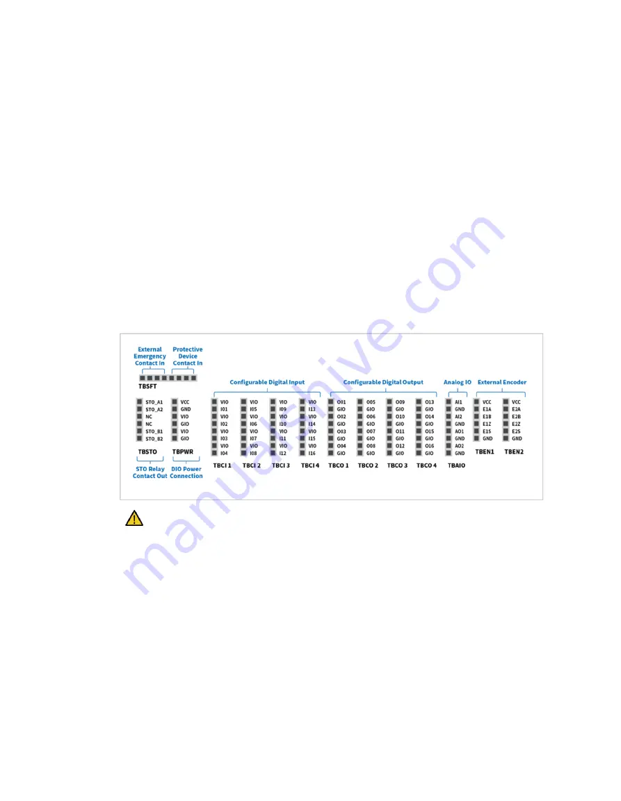
connected. The controller I/O consists of the following six
units:
•
Terminal Block for Safety Contact Input (TBSFT): Used to connect devices required for
emergency stopping and protective stopping
•
Terminal Block for Safety Contact Output (TBSTO): Used to connect a power switch
•
Terminal Block for Digital I/O Power (TBPWR):
•
Configurable Digital IO Block (TBCI1- 4, TBCO1– 4): Used to connect peripherals required for
robot operation
•
Terminal Block for Analog I/O (TBAIO):
•
Terminal Block for Encoder Input (TBEN1, TBEN2)
The figure below depicts the electric interface layout of the controller interior.
Caution
Turn off the power when connecting terminals to the controller I/O to prevent product damage
and breakdown.
Doosan Robotics will not compensate any product damage caused by inappropriate terminal
connection or user negligence.
Make sure to turn off the external power source when turning off the controller power.
Summary of Contents for H2017
Page 1: ...1 Manual Version 2 1 Software Version 2 7 1 ...
Page 29: ...29 2 5 3 Robot operating space M0609 ...
Page 30: ...Doosan Robotics Installation Manual v2 1 30 ...
Page 31: ...31 M0617 ...
Page 32: ...Doosan Robotics Installation Manual v2 1 32 ...
Page 33: ...33 M1013 ...
Page 34: ...Doosan Robotics Installation Manual v2 1 34 ...
Page 35: ...35 M1509 ...
Page 36: ...Doosan Robotics Installation Manual v2 1 36 ...
Page 37: ...37 H2017 ...
Page 38: ...Doosan Robotics Installation Manual v2 1 38 ...
Page 39: ...39 H2515 ...
Page 40: ...Doosan Robotics Installation Manual v2 1 40 ...
Page 42: ...Doosan Robotics Installation Manual v2 1 42 M1013 M1509 ...
Page 119: ...119 B 2 Europe Machinery Directive Attestation of Conformity ...
Page 120: ...Doosan Robotics Installation Manual v2 1 120 ...
Page 121: ...121 B 3 Europe EMC Directive Attestation of Conformity ...
Page 122: ...Doosan Robotics Installation Manual v2 1 122 B 4 U S NRTL Certification U S CANADA ...
Page 123: ...123 ...
Page 124: ...Doosan Robotics Installation Manual v2 1 124 B 5 Functional Safety Certification ...
Page 125: ...125 B 6 Voluntary Safety Confirmation Declaration KCs ...
Page 126: ...Doosan Robotics Installation Manual v2 1 126 ...
Page 127: ...127 ...
Page 128: ...Doosan Robotics Installation Manual v2 1 128 ...
Page 129: ...129 ...
Page 130: ...Doosan Robotics Installation Manual v2 1 130 ...
Page 161: ...161 D 1 3 Nameplate and Label ...
Page 176: ...Doosan Robotics Installation Manual v2 1 176 E 1 3 Nameplate and Label ...
Page 190: ...Doosan Robotics Installation Manual v2 1 190 ...


