


G643(E) Service Manual
Chapter 5. Engine Management System (EMS)
176
(
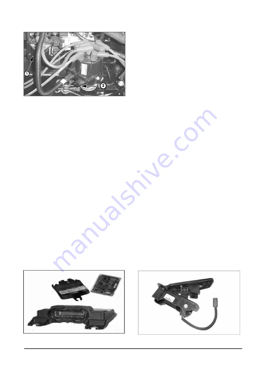
1)
Ignition Coil (
2)
Ignition Module
Figure 15. GM Ignition Module
The rising edge of the VR signal is converted to a
rising 5-volt signal by the ignition module. As the VR
signal passes back through zero volts, a falling edge
is created producing a square wave or digital signal,
similar to the signal produced by a Hall effect sensor.
This falling edge signal provides a stable engine
position reference at all engine speeds for the
SECM.
SECM
Small Engine Control Module (SECM) controller has
full authority over spark and air. the SECM has 24
pins of I/O and is fully waterproof and shock
hardened (
Figure 16
).
To optimize engine performance and drivability, the
SECM uses several sensors for closed loop
feedback information. These sensors are used by
the SECM for closed loop control in two main
categories:
•
Load/Speed
Management
•
Ignition
Management
Figure 16. Small Engine Control Module (SECM)
The SECM monitors system parameters and stores
any out of range conditions or malfunctions as faults
in SECM memory. Engine run hours are also stored
in memory. Stored fault codes can be displayed on
the Malfunction Indicator Light (MIL) as flash codes
or read by the Service Tool software through a CAN
(Controller Area Network) communication link.
Battery power (12 Vdc) is supplied through the fuse
block to the main power relay. The ignition key
switch is used to energize the main power relay. A
main power relay supplies 12 Vdc power to the
SECM, fuel lock-off, and the Smart Coil. The SECM
supplies positive voltage to the electronic throttle
actuator, oil pressure switch and the coolant
temperature sensor. Transducer or sensor power
(+5 Vdc) is regulated by the SECM and supplied to
the temperature/manifold air pressure sensor
(TMAP), throttle position sensor (TPS), and the
accelerator pedal position sensors (APP1 & APP2).
The SECM provides a constant voltage (VCC) to the
Smart Coil Driver, transducer ground for the all
sensors, and a low side driver signal controlling the
fuel lock-off and MIL.
SECM (Load/Speed Management)
Drive by wire refers to the fact that the MI-07 control
system has no throttle cable from the foot pedal
(Figure 17) to the throttle body. Instead, the SECM
is electronically connected both to the foot pedal
assembly and the throttle body. The SECM monitors
the foot pedal position and controls the throttle plate
by driving a dc motor connected to the throttle. The
dc motor actuates the throttle plate to correspond to
the foot pedal position when the operator depresses
the pedal.
The use of electronic throttle control (ETC) ensures
that the engine only receives the correct amount of
throttle opening for any given situation, greatly
improving idle quality and drivability.
Figure 17. Foot Pedal


