


•
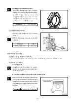
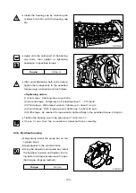
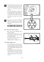
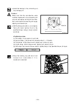
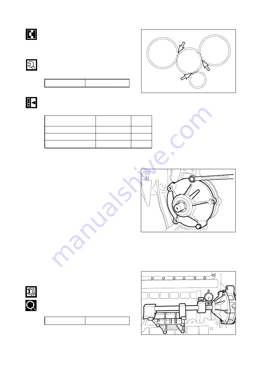
Install the idle gear by coinciding the
marks impressed on the crank gear, cam
gear, fuel injection pump drive gear, and
idle gear.
•
Install a thrust washer on the idle gear
and tighten to specified torque.
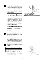
•
Check and adjust the amount of backlash
between gears using a feeler gauge.
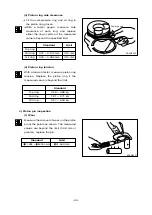
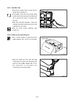
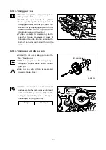
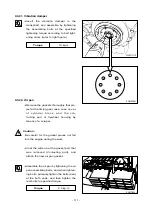
9.3.15. Injection pump flange
•
After assembling the fuel injection pump
g e a r t o t h e i d l e g e a r, t i g h t e n t h e
assembling bolts of the injection pump
flange.
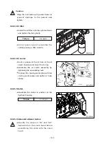
•
Mount gasket by aligning the bolt holes
with the pin holes on the bearing
housing.
•
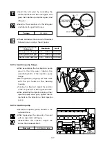
Turning the flywheel, adjust the pointer
to the 19
˚
position of the engraved scale.
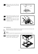
•
After adjusting the injection timing of fuel
injection pump drive gear, tighten the fix-
ing bolts in the direction of fuel injection
pump.
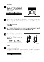
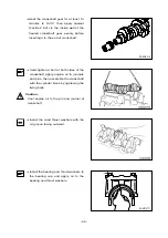
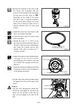
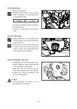
9.3.16. Injection pump
•
Install the injection pump bracket in the
cylinder block.
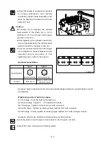
•
After measuring the amount of run-out
with an alignment setting jig,
disassemble the bracket, adjust the
shims, then reassemble it.
- 107 -
EA9M3015
Fuel injection
pump drive gear
Idle gear
Cranshaft gear
Cam
shaft
gear
Mark "0"
Mark "2"
Mark "1"
2
2
2
2
2
1
1
1
1
1
Torque
3.1 kg
.
m
Measuring position
Backlash
Limit
(between)
Cam gear & idle gear
0.16 ~ 0.28 mm 0.35 mm
Crank gear & idle gear
0.16 ~ 0.28 mm 0.35 mm
Injection pump & idle gear
0.16 ~ 0.28 mm 0.35 mm
EA9M3021
EAMD107I
Run out
0.2 mm or less
Summary of Contents for D1146
Page 1: ......
Page 57: ...7 2 Trouble Shooting 53 ...
Page 58: ... 54 ...
Page 59: ... 55 ...
Page 60: ... 56 ...
Page 61: ... 57 ...
Page 62: ... 58 ...
Page 63: ... 59 ...


