42
OPTIONS
7/53
BUNDED BASE
DESCRIPTION
This machine can be fitted with bund equipment to contain leakages
and spillages, which occur within the machine enclosure.
The bund will contain all fluids normally installed in the machine, plus
an additional 10%.
When fitted with bund, the machine must only be operated when level.
Drains for engine coolant, engine oil and compressor oil, fuel tank and
bunded base drains are located at the left rear side of the machine.
Bunded based to be drained daily
DRAINING OF CONTAMINATED FLUIDS
Contaminated fluid must be removed by authorized personnel only.
Captured fluids can be drained from the bund by removing the plug or
uncoupling the flexible pipe secured at the left side of the machine. The
plug must be re-sealed after draining. The flexible pipe must be re-
secured after draining.
DRAINING OF MACHINE FLUIDS
During maintenance operations drain machine fluids using the drain
ports indicated.
GENERATOR
SAFETY
Refer to the SAFETY SECTION in this manual.
GENERAL INFORMATION
Rated output
4,8 kW @ 0,8 Power factor
(PF) lagging
Rated voltage
110V 1ph or 230V 1ph or 230V 3ph or
400V 3ph + 230V 1ph @ 3000 revs
min-1
Voltage regulation
+/- 6%
Maximum continuous output
6 kVA @ 0,8 PF
Rotor type
Brushless
(110/230V 1ph)
Rotor type
Rotating armature with sliprings
(230V 3ph / 400V 3ph + 230V 1ph)
De-rating factors at 0.8 pf continuous load:
Air in temp 20°C
Continuous
Air in temp 30°C
5,7 KVA @ 0.8 p.f continuous
Air in temp 46°C
4,5 KVA @ 0.8 p.f continuous
De-rating factors for intermittent load:
Air in temp 20-35°C,55 mins/hr @ 0.8, 5 mins off load
Air in temp 35-40°C,50 mins/hr @ 0.8, 10 mins off load
Air in temp 40°C + ,45 mins/hr @ 0.8, 15 mins off load
Socket outlets:
110V 1ph & 230V 1ph
1 x 32 amperes
2 x 16 amperes
230V 3ph
1 x 16 amperes
400V 3ph + 230V 1ph
400V 3ph = 1 x 16 amperes
230V 1ph = 2 x 16 amperes
Earth leakage protection is provided by a single residual current
device. Miniature circuit breakers (MCB) are fitted to provide both
overcurrent and short circuit protection for the generator.
Each socket outlet is protected by a spring loaded weather–proof
cover.
OPERATING INSTRUCTIONS
A mode selector switch is provided to switch the machine between
compressor and generator mode.
When the switch is in the
Generator
position the normally-open
solenoid valve switches to the closed position and air in the line to the
engine speed control cylinder vents to the atmosphere via the solenoid
exhaust port. This causes the cylinder to move to its maximum speed
position. The engine will now maintain maximum speed as the air line
from the pressure regulator valve to the solenoid valve is now closed.
When the switch is returned to the
Compressor
position, the solenoid
valve is de-energised thus returning it to its normally open position. The
engine speed cylinder would then respond via the pressure regulator
valve according to the air demand.
When connecting electrical equipment to any of the socket outlets, it is
recommended that the appropriate MCB is in the
OFF
position before
making the connection, switching the MCB to the
ON
position
immediately prior to using the equipment.
WARNING: Major leakages or spillages must be drained before
the machine is towed.
CAUTION:
Do not start or stop the machine with the compressor/
generator mode switch in the
Generator
position.
Summary of Contents for 7/53
Page 2: ......
Page 4: ......
Page 11: ...DECALS 7 7 53 Engine oil drain...
Page 15: ...GENERAL INFORMATION 11 7 53 7 53 FIXED HEIGHT RUNNING GEAR 7 53 VARIABLE HEIGHT RUNNING GEAR...
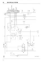
Page 34: ...30 ELECTRICAL SYSTEM 7 53 7 53...
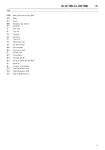
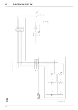
Page 36: ...32 ELECTRICAL SYSTEM 7 53 7 53...
Page 44: ...40 OPTIONS 7 53 WATER SEPARATOR MAINTENANCE FIGURE 4 FIGURE 5 FIGURE 1 FIGURE 2 FIGURE 3...
Page 58: ......
Page 59: ......
Page 60: ......

