MAINTENANCE
23
7/53
AIR FILTER ELEMENTS
The air filter should be inspected regularly (refer to the
SERVICE/
MAINTENANCE CHART
) and the element replaced when the
restriction indicator shows red or every 6 Months (500 hours),
whichever comes first. The dust collector box(es) should be cleaned
daily (more frequently in dusty operating conditions) and not allowed to
become more than half full.
Removal
Clean the exterior of the filter housing and remove the filter element by
releasing the nut.
Inspection
Check for cracks, holes or any other damage to the element by holding
it up to a light source, or by passing a lamp inside.
Check the seal at the end of the element and replace if any sign of
damage is evident.
Reassembly
Assemble the new element into the filter housing ensuring that the seal
seats properly.
Reset the restriction indicator by depressing the rubber diaphragm.
Assemble the dust collector box parts, ensuring that they are correctly
positioned.
Before restarting the machine, check that all clamps are tight.
VENTILATION
Always check that the air inlets and outlets are clear of debris etc.
COOLING FAN DRIVE
Periodically check that the fan mounting bolts in the fan hub have not
loosened. If, for any reason, it becomes necessary to remove the fan
or re-tighten the fan mounting bolts, apply a good grade of
commercially available thread locking compound to the bolt threads
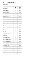
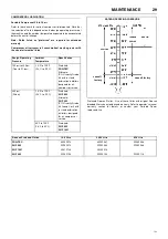
and tighten to the torque value shown in the
TORQUE SETTING
TABLE
later in this section.
The fan belt(s) should be checked regularly for wear and correct
tensioning.
FUEL SYSTEM
The fuel tank should be filled daily or every eight hours. To minimise
condensation in the fuel tank(s), it is advisable to top up after the
machine is shut down or at the end of each working day. At six month
intervals drain any sediment or condensate that may have
accumulated in the tank(s).
FUEL FILTER WATER SEPARATOR
If the fuel filter water separator contains a filter element, it should be
replaced at regular intervals (see the
SERVICE/MAINTENANCE
CHART
).
HOSES
All components of the engine cooling air intake system should be
checked periodically to keep the engine at peak efficiency.
At the recommended intervals, (see the
SERVICE/MAINTENANCE
CHART
), inspect all of the intake lines to the air filter, and all flexible
hoses used for air lines, oil lines and fuel lines.
Periodically inspect all pipework for cracks, leaks, etc. and replace
immediately if damaged.
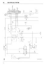
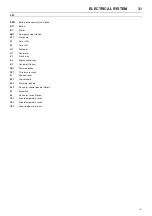
ELECTRICAL SYSTEM
Inspect the safety shutdown system switches and the instrument panel
relay contacts for evidence of arcing and pitting. Clean where
necessary.
Check the mechanical action of the components.
Check the security of electrical terminals on the switches and relays i.e.
nuts or screws loose, which may cause local hot spot oxidation.
Inspect the components and wiring for signs of overheating i.e.
discolouration, charring of cables, deformation of parts, acrid smells
and blistered paint.
BATTERY
Keep the battery terminals and cable clamps clean and lightly coated
with petroleum jelly to prevent corrosion.
The retaining clamp should be kept tight enough to prevent the battery
from moving.
PRESSURE SYSTEM
At 500 hour intervals it is necessary to inspect the external surfaces of
the system (from the airend through to the discharge valve(s))
including hoses, tubes, tube fittings and the separator tank, for visible
signs of impact damage, excessive corrosion, abrasion, tightness and
chafing. Any suspect parts should be replaced before the machine is
put back into service.
TYRES/TYRE PRESSURE
See the
GENERAL INFORMATION
section of this manual.
RUNNING GEAR/WHEELS
Check the wheel nut torque 20 miles (30 kilometres) after refitting the
wheels. Refer to the
TORQUE SETTING TABLE
later in this section.
Lifting jacks should only be used under the axle.
The bolts securing the running gear to the chassis should be checked
periodically for tightness (refer to the
SERVICE/MAINTENANCE
CHART
for frequency) and re-tightened where necessary. Refer to the
TORQUE SETTING TABLE
later in this section.
CAUTION:
Never remove and replace element(s) when the machine
is running.
CAUTION:
NEVER clean by blowing air inwards.
WARNING: Always disconnect the battery cables before per-
forming any maintenance or service.
Summary of Contents for 7/53
Page 2: ......
Page 4: ......
Page 11: ...DECALS 7 7 53 Engine oil drain...
Page 15: ...GENERAL INFORMATION 11 7 53 7 53 FIXED HEIGHT RUNNING GEAR 7 53 VARIABLE HEIGHT RUNNING GEAR...
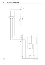
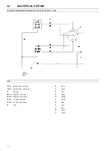
Page 34: ...30 ELECTRICAL SYSTEM 7 53 7 53...
Page 36: ...32 ELECTRICAL SYSTEM 7 53 7 53...
Page 44: ...40 OPTIONS 7 53 WATER SEPARATOR MAINTENANCE FIGURE 4 FIGURE 5 FIGURE 1 FIGURE 2 FIGURE 3...
Page 58: ......
Page 59: ......
Page 60: ......

