Resource Identifier: 100325
Revision 1.0
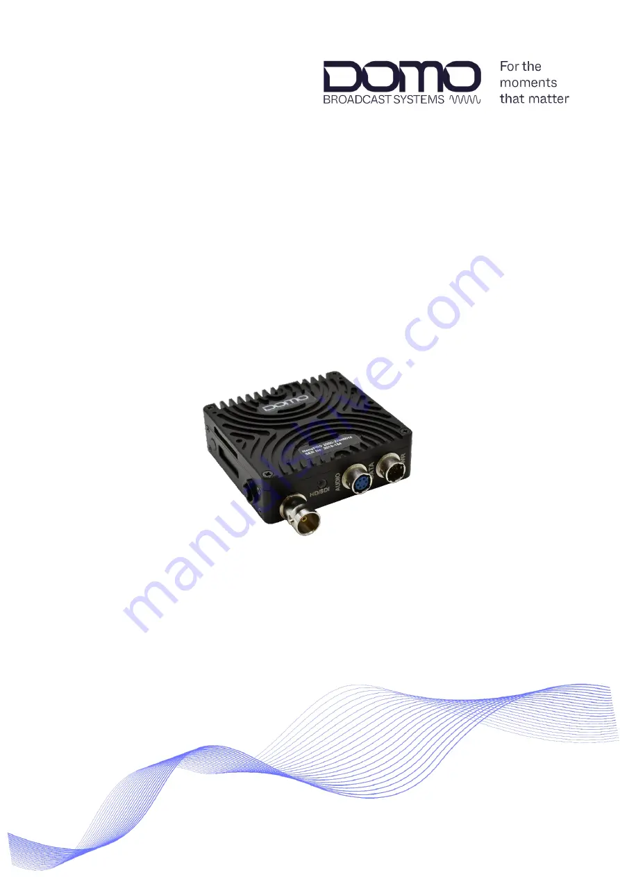
DBS Nano PRO Transmitter User Guide
Commercial in Confidence
Page 1: ...Resource Identifier 100325 Revision 1 0 DBS Nano PRO Transmitter User Guide Commercial in Confidence ...
Page 2: ...are responsible for maintaining the equipment or system 0 3 Notice about this Publication While every attempt is made to maintain the accuracy of the information in this product manual it is subject to change without notice Performance specifications are included for guidance All particulars are given in good faith actual performance may vary 0 4 Text Conventions This document uses these conventio...
Page 3: ...ms Note A notice to draw attention to something or to supply additional information 0 6 Copyright This document contains information that is proprietary to Domo Tactical Communications DTC Limited trading as Domo Broadcast Systems DBS Any copying or reproduction in any form whatsoever is prohibited without the written permission of DTC 2022 Copyright Domo Tactical Communications DTC Limited All ri...
Page 4: ...4 Licensing Options 2 3 2 5 Variants 2 3 3 Connections Controls and Indicators 3 4 3 1 Introduction 3 4 3 2 Antenna Panel 3 4 3 3 Bottom Panel 3 5 3 4 OLED Display and Control 3 6 3 5 USB Micro 3 6 3 6 Antenna Adaptor Camera Mount Bracket 3 7 3 7 Battery Mount Clamshell 3 8 3 8 Pinout 3 9 4 Getting Started 4 11 4 1 Introduction 4 11 4 2 Power 4 11 4 3 Control 4 11 4 4 Device Controller 4 12 5 Devi...
Page 5: ...s Conversion 7 38 7 2 Software Upgrade via a Terminal Program 7 39 8 Appendix B After Sales Support 8 40 8 1 Documentation and Software 8 40 8 2 Contact Technical Support 8 40 8 3 Using the DTC RMA Service 8 40 9 Appendix C Safety and Maintenance 9 42 9 1 Cautions and Warnings 9 42 9 2 Repairs and Alterations 9 43 9 3 Caring for your Equipment 9 43 9 4 Charging 9 43 9 5 Working with Lithium Batter...
Page 6: ... for the first time Optional lightweight low power consumption amplifiers are also available for even greater range capability The transmitter employs ultra low latency High Profile H 264 MPEG 4 AVC encoding for excellent image quality retention over the wireless link and supports SDI and HD SDI video input formats up to 1080p50 59 The DBS Nano PRO TX is supplied in a slimline fan cooled aluminium...
Page 7: ...Section 8 2 2 2 Parts List These items will be in the package Part Number Description Primary Unit DBS Nano PRO Transmitter see variants Section 2 5 CAB0008 XLR analogue audio cable CAB0009 Power and control cable 2 3 Accessory Options If you have purchased any of these items they will also be in the package Part Number Description BAMP 1W 200250 Barrel Booster Amplifier 1W 2 00 2 50GHz BAMP 1W 32...
Page 8: ...H 264 Encoding Optional Licenses 4 2 2 H 264 Profile Dual Pedestal SDI Ancillary Data 2 5 Variants This part number will identify the product it is also on the label Part Number Description DBSNPROTX 198270 DBS Nano PRO Transmitter 1 98 2 70GHz DBSNPROTX 300370 DBS Nano PRO Transmitter 3 00 3 70GHz DBSNPROTX 440500 DBS Nano PRO Transmitter 4 40 5 00GHz DBSNPROTX 550600 DBS Nano PRO Transmitter 5 5...
Page 9: ...p identify all the connections and interfaces of the product needed to install control and monitor the device 3 2 Antenna Panel No Item Connection 1 SMA jack female RF power output Ensure power output is not enabled before attaching the antenna CAUTION Antenna should be finger tight only to avoid damage to the connector or internal components 2 RF Status LED Tri colour LED indicator Amber booting ...
Page 10: ...ed 3 6 way Hirose female Analogue audio left right input See Section 3 8 1 for pinout CAB0008 provides two XLR connections for an audio source 4 6 way Hirose male Power data and control input See Section 3 8 2 for pinout CAB0009 provides an XLR connection for a power source and a DB9 for control BNC Interface Note The BNC input connector is a changeable screw fit interface This can be swapped for ...
Page 11: ...ruct or allow any objects to enter this space 2 OLED display Integrated display screen for status and control of commonly used parameters See Chapter 6 for description of operation 3 Control button OLED display cancel back button 4 Control button OLED display navigation select edit button 3 5 USB Micro On the side panel there is a USB micro control port socket for configuring the unit using the De...
Page 12: ...t The optional antenna adaptor bracket allows the SMA socket to be adapted to an N type socket for antennas with N type connectors as illustrated in Figure 3 1 Figure 3 1 Bracket Showing N Type Adaptor The optional antenna adaptor bracket also has a Hot Shoe wedge to allow the Nano PRO TX to mount to any camera with this fitting as illustrated in Figure 3 2 Figure 3 2 Bracket Showing Camera Mount ...
Page 13: ... Page 3 8 3 7 Battery Mount Clamshell DBS offer a clamshell housing accessory which will allow the Nano PRO TX to be mounted to a camera battery see Section 2 3 An illustration of a V mount clamshell is given in Figure 3 2 If this is a requirement please contact DBS to arrange assembly and integration Figure 3 3 Nano PRO TX Clamshell V Mount Option ...
Page 14: ... Pinout 3 8 1 AUDIO Nano Tx Hirose 6 way receptacle female HR10 7R 6S 73 Pin Function 1 Audio Left 2 Audio Left 3 Gnd 4 Audio Right 5 Audio Right 6 Gnd CAB0008 Hirose 6 way plug male HR10 7P 6P 73 Pin Function 1 Audio Left 2 Audio Left 3 Gnd 4 Audio Right 5 Audio Right 6 Gnd 3 way XLR female x 2 RS 405 590 Pin Function 1 Audio Left Right 2 Audio Left Right 3 Gnd ...
Page 15: ... 7R 6P 73 Pin Function 1 Gnd 2 Vout 12V 3 RS 232 Data Rx 4 Vin 6 17VDC 12V nom 5 RS 232 Ctrl Tx 6 RS 232 Ctrl Rx CAB0009 Hirose 6 way plug female HR10 7P 6S 73 Pin Function 1 Gnd 2 Vout 12V 3 RS 232 Data Rx 4 Vin 6 17VDC 12V nom 5 RS 232 Ctrl Tx 6 RS 232 Ctrl Rx 4 way XLR male RS 457 869 Pin Function 1 Gnd 4 Vin 6 17VDC 12V nom 9 way D sub female RS 765 9555 Pin Function 2 RS 232 Ctrl Tx 3 RS 232 ...
Page 16: ...h their product It will explain software installation instructions for any relevant applications 4 2 Power DBS Nano PRO TX does not have a power switch it is powered up as soon as the power source is connected Before removing power ensure the device is not in sleep mode see Section 5 3 1 4 3 Control The Nano PRO TX can be controlled via the OLED display explained in detail in Chapter 6 or via Devi...
Page 17: ...oller comes as an executable installer package which is available from DTC s Watchdox facility see Section 8 1 Double click the executable and follow prompts as directed to install this application on your PC On successful installation a desktop shortcut will be placed on your desktop 4 4 3 Communications Ensure your transmitter is powered up and connected to a PC by USB or serial using CAB0009 IM...
Page 18: ... All rights reserved Commercial in Confidence Page 4 13 Select the device connection depending on the physical interface and select the USB ID number or serial port com port as applicable Click Connect to establish communications Device Controller reads the Nano PRO TX settings and opens the primary page ...
Page 19: ...om your transmitter IMPORTANT Not all settings and views in Device Controller will be applicable to the DBS Nano PRO TX Only applicable settings will be explained in this chapter If the Device Controller menu shows a lock symbol next to a feature this means that it is not available for your device or that it is missing a license 5 2 Primary Page The Primary page allows quick configuration of key p...
Page 20: ...atus The RF icon on the left of the panel will allow you to quickly set RF power on or off The green connection icon on the left of the panel provides a quick disconnect option without any warnings 5 2 4 Swich Panel The switch panel provides access to Advanced settings Engineer options Upload options and Quit application The Advanced pages give access to the preset configurations for the Nano PRO ...
Page 21: ...ption Operational state Active The unit is fully powered and in an operational state Standby The unit is using less power but can be brought back to operation rapidly Sleep The unit is consuming the least amount of power but needs to be woken before being able to operate fully ASI input On Enables the re multiplexing of an ASI stream on the SDI input Relay disables local services and only passes A...
Page 22: ...ter and allow the device to cool It may be necessary to provide further heatsinking to prevent overheating 5 3 3 Unit Actions Name Description Restore to Factory Click to restore the device to factory default settings Switch to 8 16 Configs Click to switch between 8 and 16 preset configurations if required Reset Device Click to perform a power cycle on the device 5 3 4 Licensed Unlicensed Features...
Page 23: ...tings 5 4 1 Modulation Settings Name Description Modulation output This switch controls RF power output Output frequency Set the output frequency of operation This must be in the frequency band of the device see variants Section 2 5 This can be set in 125kHz steps Output power Power levels up to 100mW can be set for the TX Low power outputs will run cooler CAUTION When an external power amplifier ...
Page 24: ...ulation 5 4 2 DVB T Settings Name Description Dual pedestal Dual Pedestal mode is an optional license feature that will double the bitrate by using two adjacent COFDM channels e g 8MHz in dual pedestal mode will give a nominal bandwidth of 16MHz See Figure 5 1 Bandwidth Higher bandwidths provide better data throughput but shorten range Constellation QPSK less user data more robust more range 16QAM...
Page 25: ...ision 1 0 DBS Nano PRO Transmitter User Guide Copyright 2022 Domo Tactical Communications DTC Limited All rights reserved Commercial in Confidence Page 5 20 Figure 5 1 Dual Pedestal Spectrum Analyser Plot ...
Page 26: ...ame Description Audio source The Nano PRO TX supports a balanced analogue audio input or SDI embedded audio Audio encoder Higher audio encoding quality uses more available bandwidth Audio sync Set to Yes to synch the audio to the video Set to Early for the audio to be earlier than the video Audio sample rate Generally higher rates produce better audio quality MPEG audio bitrate Generally higher bi...
Page 27: ...ommercial in Confidence Page 5 22 5 5 2 Analogue Audio IMPORTANT Microphone gain and power settings must be controlled via the OLED display Configuration Audio settings see Section 6 3 2 5 5 3 SDI Audio SDI provides 16 channels of embedded audio in four groups of two pairs This should be left at default unless an advanced user ...
Page 28: ...ercial in Confidence Page 5 23 5 6 Advanced Video Page Click Advanced on the primary page and select Video Use the scroll bar to see all the settings 5 6 1 Video Settings Name Description Video source SDI is the only valid option for the Nano PRO TX Video source format Select the video source format that matches the camera input ...
Page 29: ... displayed If you select Full then you will see all horizontal pixels if you select 1 2 you will see a down sampled picture which requires much less bitrate to encode Sub vert resolution This is the fraction of the vertical resolution that will be displayed If you select Full then you will see all vertical lines if you select 1 2 you will see a down sampled picture which requires much less bitrate...
Page 30: ...ercial in Confidence Page 5 25 5 6 2 SDI Video This should be set to Automatic unless an advanced user This provides support for HD SDI formats over a 3G SDI dual stream video input 5 6 3 Compatibility This should be left at No unless an advanced user Set to Yes as a compatibility requirement for some video management systems VMS ...
Page 31: ...Click Advanced on the primary page and select Misc Use the scroll bar to see all the settings 5 7 1 Miscellaneous Options Name Description Data input RS 232 data can be passed over the COFDM link Data baud rate The speed of data transfer The transmit receive devices must use the same setting Data format The data and parity bit The transmit receive devices must use the same settings ...
Page 32: ...attern or emits a tone if video or audio is missing Auto video displays the pattern if video is missing Auto audio emits a tone if audio is missing AV sync displays an AV sync pulse only Pattern mode This is what will appear on the screen in the event of no video input or if generator control is set to Force on OSD position Sets the position of the on screen display OSD which will appear on your s...
Page 33: ...e This is an identifier for the service in the Transport Stream TS The TS can have many services The receiver must align with this name for the service to be decoded Program number A number to identify the Program Each program in a transport stream is described by a PMT Must be 1 0 no service PMT PID PCR PID Video PID Audio PID Data PID Metadata PID ANC PID Each table or elementary stream in a tra...
Page 34: ...ial_number ESN license_number lic e g AK000143 8e417fdb 133444 lic 5 8 2 Software Upgrade When you need to do a software upgrade the upgrade file will be made available to you by DBS The upgrade file for the Nano PRO TX will be in the format d1600_vx x all Note Software upgrades can also be performed serially via a terminal program see Section 7 2 5 8 3 Upgrade Process To upload a new license file...
Page 35: ... either side of the display Either button can be used to wake up the screen if it is in sleep mode display off Left Button The left button is the cancel back button Press this button to return to the previous menu or cancel changes to a setting The left button will also switch between the frequency preset display and the top level menu Right Button The right button is the navigate select edit butt...
Page 36: ...is the first Status parameter Press the up down arrow buttons to scroll through the Status menu The status categories are Frequency and preset RF power output and modulation Video source and lock Audio input and encoder From the Status menu press the left button to access the top level menu and the up down arrow to scroll through the options Status press the right button to take you back to the St...
Page 37: ... 5 4 1 FEC As for Device Controller see Section 5 4 2 Guard Interval As for Device Controller see Section 5 4 2 Polarity Set this to Inverted if you need to invert the COFDM spectrum to align with third party equipment When operating with DBS products this is not necessary and should be left at Normal Dual Ped As for Device Controller see Section 5 4 2 Menu Sub menu Notes Video Format As for Devic...
Page 38: ...troller see Section 5 5 1 Mic Gain L 0dB 10dB 20dB 30dB gain can be applied Mic Gain R 0dB 10dB 20dB 30dB gain can be applied Gain Adj L Fine gain adjustment Gain Adj R Fine gain adjustment Mic P48 Provides 48V phantom power to an attached microphone if required Menu Sub menu Notes Data Input As for Device Controller see Section 5 7 1 Baud Rate As for Device Controller see Section 5 7 1 Format As ...
Page 39: ...d Commercial in Confidence Page 6 34 6 3 3 Preset Press the right button to select the Preset menu Press the left button to exit Note Up to sixteen preset configurations can be stored and configured Sub menu Notes Preset Number The preset number is the currently active preset Preset Name The preset name cannot be configured ...
Page 40: ...isplays the OLED display software version See Section 6 4 for upgrade details Serial Number Displays the electronic serial number ESN As for Device Controller see Section 5 3 2 RF Calibration CAUTION This menu is for DBS Engineering only Access will stop RF transmission Remote Control Press Enter to establish serial RS 232 communications to a PC This will allow Device Controller communications see...
Page 41: ...d power control cable CAB0009 and connect the 9 way D sub connector to a PC serial port or via a serial to USB adaptor 2 Open a terminal emulator program on the PC e g Tera Term and configure the following serial port settings Port as connected Baud rate 115200 Data 8 bit Parity none Stop 1 bit Flow control Xon Xoff 3 Power up the unit and press the u key The terminal display should read the follo...
Page 42: ...fidence Page 6 37 4 Press uppercase Y to erase the flash 5 On the terminal menu click File Send file and browse to the location of the upgrade file Ensure the Binary box is not ticked and select Open to start the upgrade 6 The upgrade progress will be displayed 7 An Upgrade Successful message will appear on completion and the unit will reboot ...
Page 43: ...on to the modulator RF output Transmitters without amplifiers have a maximum RF output of 20dBm 100mW When calculating do not convert the equivalent watt value until after the sum has been done i e 20dBm 3dBm 17dBm 50mW dBm Watts dBm Watts 0 1 0mW 17 50mW 1 1 3mW 18 63mW 2 1 6mW 19 79mW 3 2 0mW 20 100mW 4 2 5mW 21 126mW 5 3 2mW 22 158mW 6 4mW 23 200mW 7 5mW 24 250mW 8 6mW 25 316mW 9 8mW 26 398mW 1...
Page 44: ... couple of minutes to complete Progress is shown by an increasing number of characters Once complete Download code will be shown in Tera Term 4 Select File Send File and ensure the Binary checkbox is checked as shown below Select the upgrade file and click Open 5 A progress box will appear as shown below This will disappear once the file transfer is complete Progress is also shown by an increasing...
Page 45: ...otactical com no restricted content 8 3 Using the DTC RMA Service 8 3 1 Contact DTC If there is a problem and our technical support team have been unable to resolve the issue email dtc rma domotactical com US or solent customerhub domotactical com UK ROW to request a Return Material Authorisation RMA form Note Alternatively use the online form at https www domotactical com support 8 3 2 Complete a...
Page 46: ...Commercial in Confidence Page 8 41 8 3 4 Put the RMA Number on the Box Clearly mark the outside of the shipping box with the RMA number If an RMA number is not present on the shipping box receiving will be unable to identify it and it might be returned 8 3 5 Send the Box to DTC Send the box using your normal shipping process ...
Page 47: ...he product There are no user serviceable parts inside Environment The equipment should not be used in hazardous or corrosive atmospheres Users are reminded of the necessity of complying with restrictions regarding the use of radio devices in fuel depots chemical plants and locations where explosives are stored and or used Lightning strike There is a risk of lightning strike to antennas The equipme...
Page 48: ...s chargers and adapters designed specifically for your make and model unit Do not attempt to charge a wet unit or battery pack Do not charge the unit or battery pack near anything flammable Stabilize the battery pack to room temperature 22 C before charging Do not charge units and or battery packs on wet or unstable surfaces Do not leave units and or batteries in chargers for excessive periods 9 5...
Page 49: ...dered separate waste and should not be allowed to enter the normal waste stream Either return to the seller or deliver to an approved re cycling facility 9 6 Cleaning Turn off the unit and remove batteries if applicable before maintenance Use a clean soft damp cloth to clean the unit A microfiber cloth is recommended Do not use alcohol or cleaning solutions to clean the unit Do not immerse the uni...