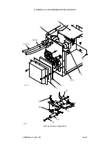
APPENDIX B : COMPRESSOR DRIVEN AIRDRYER
20950 Issue 1 April 98
B--37
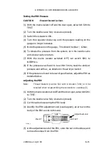
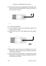
(12) Insert the allen key into the locking screw, and turn clockwise to
lock.
Note:
If the pressure adjusts, and the locking screw does not seem to lock,
remove the locking screw completely and refit the other way round.
If this is necessary, repeat steps 10 to 12).
(13) The PRV is now set. To release the pressure from the system, turn
the needle valve anti--clockwise by one turn.
(14) Switch the mains isolator OFF, and set switch SW1 to NORMAL.
(15) Apply Loctite activator to the end of the PRV thread , leave for 10
minutes, then apply Loctite 542 to the thread and refit the elbow to
within 1 to 2 turns of the end of the thread.
(16) Reconnect the nut to the elbow and cable tie the PRV back in place.
(17) Reset the airdryer’s pressure and airflow as detailed in the airdryer
test lit.
Needle Valve Refurbishment and Adjustment
WARNING:
The airdryer must be switched off and power
removed.
The door must be open.
Test equipment to measure air flow and humidity will be required. See
Pg. B--44 for details.
(1) Unscrew the needle and withdraw from the valve body.
(2) Check needle is clean. Clean and check the ’O’ring -- replace if
necessary.
(3) Refit the needle into the valve body.
(4) Screw the needle into the valve until the valve is closed. Do not
over--tighten the needle.
(5) Consult the air flow meter chart and determine the meter
graduations corresponding to air flows of 2.0 and 2.2
litres/minute.
(6) Connect the air flowmeter to the air tube in the print head. Support
the flow meter in a vertical position.
(7) Carefully unscrew the needle and set the air flow indicated by the
meter to between 2.0 and 2.2 litres/minute. Remove the meter.
Note:
Any instability in the ink jet should be properly investigated. If the
air flow rate from the dryer does interfere with the ink jet, reduce
the air flow (screw in the needle) until the interference ceases.
Summary of Contents for A-SERIES
Page 1: ...DOMINO A SERIES INK JET PRINTER OPERATION AND MAINTENANCE MANUAL ...
Page 6: ... 6 27080 Issue 1 Sept 98 ...
Page 8: ... 8 27080 Issue 1 Sept 98 ...
Page 10: ... 10 27080 Issue 1 Sept 98 ...
Page 12: ...HEALTH AND SAFETY 1 2 27080 Issue 1 August 98 ...
Page 18: ...HEALTH AND SAFETY 1 8 27080 Issue 1 August 98 ...
Page 20: ......
Page 21: ......
Page 22: ......
Page 36: ...OPERATION 3 2 27080 Issue 1 August 98 ...
Page 55: ...DISPLAY MESSAGES AND FAULT FINDING 4 2 27080 Issue 1 August 98 ...
Page 76: ...REFERENCE 5 4 27080 Issue 1 August 98 ...
Page 136: ...PRINTER DESCRIPTION 6 20 27080 Issue 1 September 98 ...
Page 137: ...DESCRIPTION 27080 Issue 1 August 98 6 21 Wiring Diagram 37700W Iss 1 PELTI ER ...
Page 138: ...DESCRIPTION 6 22 27080 Issue 1 August 98 ...
Page 140: ...MAINTENANCE 7 2 27080 Issue 1 Sept 98 ...
Page 142: ...MAINTENANCE 7 4 27080 Issue 1 Sept 98 ...
Page 156: ...MAINTENANCE 7 18 27080 Issue 1 Sept 98 ...
Page 158: ...REPAIR 8 2 27080 Issue 1 Sept 98 ...
Page 192: ...REPAIR 8 36 27080 Issue 1 Sept 98 ...
Page 208: ...SPARES AND ACCESSORIES 9 16 27080 Issue 1 Sept 98 Electronics Inner Door 1 2 3 4 5 6 7 ...
Page 212: ...SPARES AND ACCESSORIES 9 20 27080 Issue 1 Sept 98 ...
Page 214: ...OPTIONS 10 2 27080 Issue 1 Sept 98 ...
Page 240: ...OPTIONS 10 28 27080 Issue 1 Sept 98 ...
Page 242: ...APPENDIX A INSTALLATION A 2 27080 Issue 1 Sept 98 ...
Page 261: ...APPENDIX B COMPRESSOR DRIVEN AIRDRYER B 2 20950 Issue 1 April 98 ...
Page 311: ...APPENDIX B A SERIES AIR DRIVEN AIRDRYER B 2 20951 Issue 1 Apr 98 ...
Page 313: ...APPENDIX B A SERIES AIR DRIVEN AIRDRYER B 4 20951 Issue 1 Apr 98 ...


