background image

32

3. After  approximately  10  seconds  press  knob  (E)  several  times.  After

ignition,  hold  down  knob  (B)  for  a  further  20-30  seconds  before

releasing.
The flame can be controlled by aperture (C).
Should no ignition occur, repeat the ignition process after 1 minute.
(This  could  take  longer  than  10  seconds  if  the  unit  has  been  out  of

operation  for  a  prolonged  period  or  after  replacing  the  gas  cylinder.

Cause: air in the lines).

4. Once sufficient refrigeration has been obtained in the cooling tank at the

MAX position, the control knob should be turned to the MIN position by

low outside temperatures or when the refrigerator is only lightly loaded

respectively the ambient temperature is below +18°C, in order to avoid

overfreezing the contents.

12. Shutting down gas operation 

1. Close gas cylinder or pressure regulating valve.
2. Turn knob (B) clockwise to the off position.

13. Food and drink storage

Foodstuffs  and  drinks  should  always  be  sealed  when  stored  in  the

cooling unit. Thus, changes in taste and smell are avoided.
Food and drink should be so placed in the cooler so as to allow air to

circulate freely.
Do not place hot food or drinks in the cooler!
Under  no  circumstances  should  inflammable  liquids  and/or  gases  be

stored in the cooler. Explosion hazard!

14. Defrosting and measures for prolonged

periods of disuse

A build up of too much ice on the evaporator hinders cooling of the unit and

thus  reduces  effectiveness.  When  there  is  an  approximately  5-mm-thick

layer of ice build-up it is recommended to defrost the cooling unit. Thus, the

cooling unit will be turned off and any goods to be cooled removed. Never

use heated appliances, heaters, etc. to speed up the defrosting process! If

necessary, a cloth dipped in warm water can be placed on the unit to help

the defrosting process. After defrosting, clean up the defrosted water with a

clean cloth and clean the cooler containers as described in chapter 4.

GB

Summary of Contents for RC1600

Page 1: ...207 5013 04 Type JCB 1 Gebrauchsanweisung Mode d emploi Instruzioni per l uso Operating instructions Gebruiksaanwijzing Instrucciones de manejo DE AT CH LU BE CH IT CH GB NL ES IE LU 0402...

Page 2: ...ate ventilation as a failure to do this will result in component failure and possible food loss refer to relevant instructions for unit installation under point 4 Before defrosting cleaning or mainten...

Page 3: ...ed This will result in a good energy saving cooling system 5 Cleaning Prior to initial use and later after defrosting or prior to a prolonged period out of operation clean the container and lid with l...

Page 4: ...correctly Connections should be firmly made after all conductor strands are entered into the terminal posts When preparing the cable ends take care not to damage the outer sheath or the insulation sur...

Page 5: ...kwise to position 0 a slight resistance will be felt just before this position Pull out mains plug 7 D C operation Do not use any additional form of energy mains gas A safety fuse must be installed in...

Page 6: ...to reduce the pressure in the gas cylinder to the operating pressure specified on the rating plate no other pressure may be used Needle valve operated gas control taps are NOT suitable for use with t...

Page 7: ...e burner every time after connection turn on the gas at the bottle and check the gas connections for leaks by applying a soap and water solution over them and watching for bubbles which would indicate...

Page 8: ...sition 13 Food and drink storage Foodstuffs and drinks should always be sealed when stored in the cooling unit Thus changes in taste and smell are avoided Food and drink should be so placed in the coo...

Page 9: ...lace the gas filter remove the filter from the duct and replace it with a new one Any other maintenance and repair works especially those relating to the cooling aggregate and the gas burner system ma...

Page 10: ...in accordance with our guarantee conditions 18 Technical Data Gas operation butane propane Rated thermal loading 112 W 118 W Min thermal loading 89 W 86 W Connected load gas 8 1g h 8 4 g h Connection...

Page 11: ...51 Fig 1...

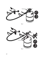
Page 12: ...52 Fig 3 Fig 2...

Page 13: ...53 Fig 5 Fig 4 joint guarnizione afdichting junta joints guarnizione afdichtingen junta...

Page 14: ...54...

Page 15: ...55...

Page 16: ...Printed by Xerox Hungary Ltd Rev 2003 12 17...

Reviews: