Dodge Charger Pursuit Upfitter Guide
39
There are four interior zones to be aware of:
•
Driver airbag deployment zone
•
Passenger airbag deployment zone
•
Side curtain airbags deployment zone
•
Side airbags (seat-mounted) deployment zone
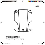
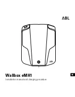
Driver Airbag Deployment Zone
407_708
1
Vertical Plane Passing Through the Center of the
Steering Wheel
4
Steering Wheel
2 475 mm (18 .7 in .)
5
Driver Airbag Retainer/Housing
3
Vertical Plane Passing Through the Maximum Rearward
Point that the Driver Airbag Cushion Reaches
6
Driver Airbag Cushion
Figure 29 Driver Airbag Dimensions
NOTE:
The illustration represents the maximum dynamic deployment shape.