1
Saw Operaton, Job Entry, Machne Setup, I/O Status
1.
When the operator selects one of these choices,
there is a group of sub-menus screens in which to
set saw parameters and/or job data. Use the
Next
Screen
function key to scroll through these group
of sub-menus screens. When the last sub-menu
screen is shown, pressing the Next Screen function
key will bring the operator back to the first screen
again. Then the operator may choose another
function.
2.
Pressing the
""
key takes the operator to a group
of sub-menus that allows the operator to set cer-
tain machine parameters. These parameters were
described in the previous section.
3.
Press the
"6"
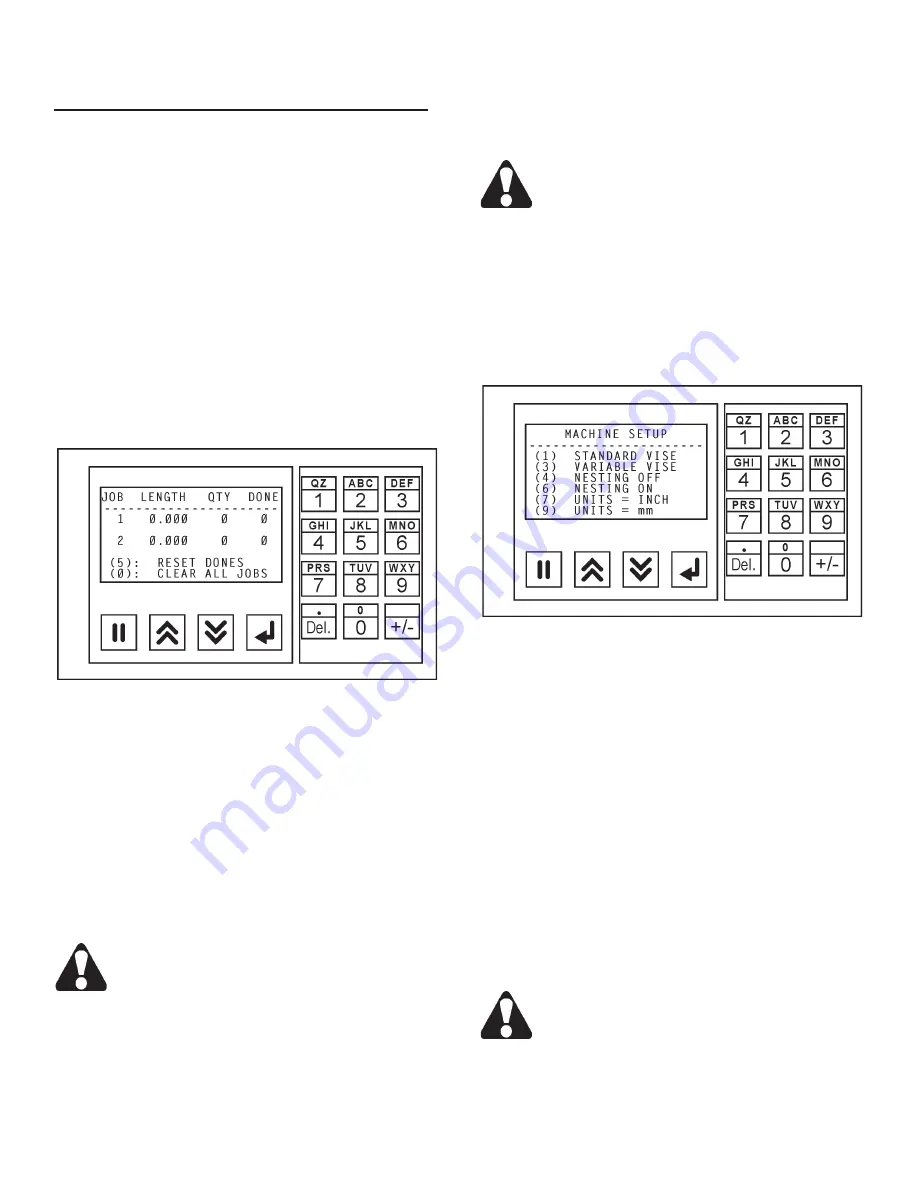
key to see the JOB ENTRY group of
sub-menu screens.
Job Entry Screen.
•
To enter data, press the
Data Entry
function key.
Then:
(a)
With the length field highlighted, enter
the length of the cut using the numeric keypad;
(b)
Press the
Accept
function key to enter the data
into memory;
(c)
With the quanitity field highlighted,
enter the number of cuts using the numeric keypad;
(d)
Press the
Accept
function key to enter the data
into memory;
(e)
With the next job's field highlighted,
continue as above;
(d)
When there is no highlighted
field, press the
Next Screen
key to move to the next
set of two (2) jobs to be programmed.
If you make an error n enterng data, just press
the Data Enter key agan, change your entry
and then press the Accept key.
•
Continue the sequence as described until all jobs
desired are entered. The operator can exit the
screen by using either the
Next Screen
or
Prevous
Screen
function keys through the sub-menu and the
operator will be brought back to the first screen.
•
To RESET DONES, press the
"5"
key on the numeric
keypad.
•
To CLEAR ALL JOBS, press the
"0" (zero)
key on
the numeric keypad.
Pressng the CLEAR ALL JOBS wll completely
clear the contents of the job lst. All data wll
be lost.
•
To skip a job or jobs in a list, set the quantities to
"0"
(zero) on those jobs to be skipped.
4.
Press the
"7"
key to see the MACHINE SETUP
group of sub-menu screens.
•
A blinling star symbol after a selection indicates that
this control is in operation.
Machine Setup Screen.
•
Press the
"1"
key on the numeric keypad for STAN-
DARD VISE pressure; press the
"3"
key for VARI-
ABLE VISE pressure (see
"Accessories"
section in
this manual for use of the Variable Vise Pressure
feature).
•
Press the
""
key on the numeric keypad for
NESTING OFF (which means the optional nesting
clamping bar is NOT operational); press the
"6"
key
for NESTING ON for vise sequence which allows
a time delay for the nesting clamping bar to clamp
the material. One vise is always clamped to keep
the bundled material in place.
•
To use and display INCH measurements, press the
"7"
key on the numeric keypad; for metric measure-
ments (mm), press the
"9"
key.
Changng between the INCH and mm settngs
wll requre that any data entered for cut length
and kerf wdth wll need to be changed also.
For example, a 6 inch cut will switch to a 6 mm
cut and vce versa.
MACHINE CONTROLS (Continued....)
Summary of Contents for DC-330NC
Page 1: ......
Page 5: ...MACHINE DIMENSIONS FLOOR PLAN INCHES 03 MILLIMETERS 1 mm...
Page 6: ...MACHINE DIMENSIONS Continued INCHES 03 MILLIMETERS 1 mm FRONT VIEW...
Page 7: ...MACHINE DIMENSIONS Continued INCHES 03 MILLIMETERS 1 mm SIDE VIEW...
Page 8: ...MACHINE FEATURES FRONT VIEW...
Page 9: ...MACHINE DIMENSIONS Continued REAR VIEW...
Page 10: ...MACHINE DIMENSIONS Continued PROXIMITY LIMIT SWITCH LOCATIONS TOP VIEW...
Page 27: ...23 LUBRICATION NEXT 2 PAGES...


