DLS 400 SOFTWARE
Page 16
Set the number of the IEEE 488 address to match the DIP switch settings on the DLS 400
rear panel (see sections 3.3 and 7.1.1 for details). Check the box(es) (A and/or B) corre-
sponding to the impairments card(s) installed in your unit, if any.
Click “OK” to return to the main control screen. Exit the software and re-launch the pro-
gram. The settings will be saved upon exiting the software, so they need not be set each
time.
4.5
Main Control Screen
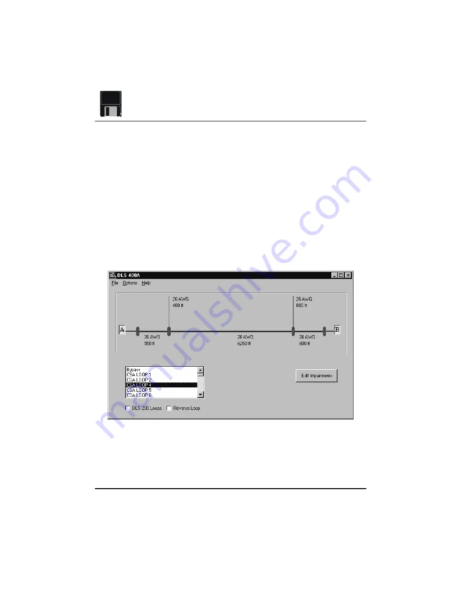
The main control screen features a schematic diagram of the simulated loop. Initially, the
diagram represents the bypass loop. Use the scroll bar to see the available loops for your
particular DLS 400 unit, and select the loop you wish to test for. The diagram will change
to correspond to the selected loop.
Figure 4.4 Control Screen showing CSA Loop #4
From the main control screen, the File, Options, and Help menus can be accessed. Click-
ing on the “Edit Impairments” button opens the Impairments Control Panel. Other options
Summary of Contents for DLS 400A
Page 1: ...Revision 0 21 September 1999 TestW rks Operating Manual DLS 400A H N HN Wireline Simulator ...
Page 2: ......
Page 12: ......
Page 63: ...ADSL NOISE GENERATOR DESCRIPTION Page 51 Figure 6 5 Cook Pulse Figure 6 6 ADSL Impulse c1 ...
Page 206: ......
Page 224: ......


