background image

25

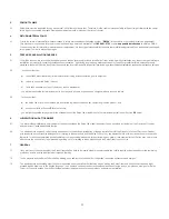
12.2 Reduced dust collection efficiency

12.3 Water entrainment in fan discharge

Extreme reduction in air flow may be caused by corrosion or abrasion to impeller sections.  
Low water level in Typhoon Central Dust Collector. Can be observed through closed glass sight. Water level below running level can be caused by:


• Open or leaky drain valve. 


• Insufficient water supply due to plugged fill valve or faulty solenoid valve 


• Solenoid valve sticking in closed position. 


• Faulty ultrasonic sensor or accumulation on sensor


• The unit is out of level. 

Rain or snow draining into exhauster housing during erection or shut down.
Excessive air flow through Typhoon Central Dust Collector. Overrating can be checked by measuring the differential pressure across the Typhoon 
Central Dust Collector. This can be done by subtracting the static pressure directly upstream of the inlet of the Typhoon Central Dust Collector from 
the static pressure directly downstream of the exhaust plenum (between the Typhoon Central Dust Collector and the exhauster). 
To stop entrainment caused by excessive air flow, increase static pressure or reduce exhauster speed.
A plugged air equalizing hose will cause the water level control box to maintain a too-high water level in the unit. Clean the hose and  
readjust the water level.
Surging of the Typhoon Central Dust Collector is a rocking of the water from end to end in the unit. This can be caused by running the unit well 
below its rated capacity.


• Surging can also be caused by a duct elbow at the Typhoon Central Dust Collector inlet. Four to five duct diameters length of straight run 

will give an even air flow at the inlet. If an elbow is required due to space limitations, turning vanes in the elbow will evenly distribute the air 
and eliminate surging.

If the unit is out of level water entrainment will result.

Summary of Contents for Typhoon TY-10000

Page 1: ...intenance Manual TYPHOON CENTRAL DUST COLLECTOR Visit our Website for more information on this product www diversitech air com www diversitech ca 1200 55th Avenue Montreal Quebec H8T 3J8 Tel 1 800 361...

Page 2: ...rk Installation 18 SECTION 9 WATER LEVEL CONTROL OPTIONS 19 SECTION 10 START UP OPERATION 19 10 1 Principles of Operation 19 10 2 Controls 19 10 3 Water Level Monitoring 20 10 4 Alarms 20 10 5 Level S...

Page 3: ...and comply with NFPA 654 Standard for the Prevention of Fire and Dust Explosions from the Manufacturing Processing and Handling of Combustible Particulate Solids and those other documents referenced t...

Page 4: ...r incorporates a fan which is close coupled and installed on top of the Typhoon Central Dust Collector or installed separately typically ground mounted and ducted to the outlet of the Typhoon Central...

Page 5: ...non metallic materials that may not present an explosion hazard As mentioned the Typhoon Central Dust Collector is primarily particularly effective for the collection of dust generated by the working...

Page 6: ...he make up water connection or by electrical controls that automatically add water as needed to compensate for evaporation and water lost as the collected dust is removed from the unit The Diversitech...

Page 7: ...the load and strapping it to the handling device Care shall be taken to ensure that the equipment is not dropped or subjected to any impact loads Any missing goods should be noted on the delivery rece...

Page 8: ...ppropriate hoisting procedure should be followed according to 5 3 Rigging and Hoisting Instructions 5 6 Middle Section Hoisting Hoisting must be done from the hoist mounts Appropriate hoisting procedu...

Page 9: ...Appropriate hoisting procedure should be followed according to 5 3 Rigging and Hoisting Instructions 5 8 Motor Blower Hoisting Hoisting must be done from the hoist mounts Appropriate hoisting procedur...

Page 10: ...ations and anchor bolts When locating the Typhoon Central Dust Collector the design engineer shall consider the many factors associated with site selection including but not limited to seismic design...

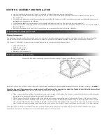
Page 11: ...Top section Blower and Motor assembly 8 2 Foundation Installation and Levelling Prepare the foundation by drilling anchor bolt holes according to the supplied dimensional drawings Install the Typhoon...

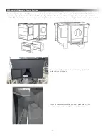
Page 12: ...hoisting instructions from Section 6 Field assembly of these sections will be as follows If the baffles of the middle section were shipped separately they will need to be installed prior to mounting...

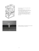
Page 13: ...flange to create a gasket with the middle section Lower the middle section carefully onto the flange of the hopper section watching for interference between intermediate sheets and baffles Set the cle...

Page 14: ...g the flange between the Typhoon Central Dust Collector middle section and the clean air transition section Locate the middle section top flange and wipe clean Place sealant tape or a thick constant b...

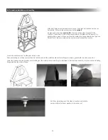
Page 15: ...er and motor can be installed As previously noted see section 8 3 the motor and blower supplied for Typhoon Central Dust Collector ships separately for installation at the jobsite With the clean air s...

Page 16: ...ill be provided with the Typhoon Central Dust Collector and will need to be installed on site Connect water inlet L piping Connect the water inlet solenoid Connect the blue pressure hose to the water...

Page 17: ...e and green wires in accordance with wiring diagram Run water level sensor wire cable to the control box and see section 8 8 for electrical connection Secure the electrical cable to body with cable cl...

Page 18: ...yphoon Central Dust Collector to the customer s drain line or sewer The customer s drain or sewer line MUST be equal to or larger in size to the drain from the Typhoon Central Dust Collector For the f...

Page 19: ...uct is designed to capture potentially combustible dust particulate from certain industrial applications using a wet filtration process When operating air and dust is drawn into the table passes throu...

Page 20: ...el will be heard When one of these alarms is present the machine will lock down and will not allow to be started Motor Overload if the main motor overload is tripped The alarm will remain until the si...

Page 21: ...3 to modify the set point value If no key is pressed within 5 seconds the interface will go back to the main screen To set the level lower limit the button 3 can be pressed Then use the button 2 and 3...

Page 22: ...cket within 20 seconds 8 Wait until the sensor flashes and changes color 9 Reinstall probe on sensor box 1 Press button 2 2 Using up down keys set the alarm to 95 3 Wait 5 seconds for the reading to b...

Page 23: ...e in your application turn the unit ON and perform a function test To do so 1 Turn switch to ON position 2 LOOK Is the unit level stable and that nothing is obstructing the extraction path Is there ad...

Page 24: ...Water Level Control Box see Section 11 2 Pre Use Checklist Every 1 Month or Specific Cleaning Cycle Exchange Water 1 Remove the water using the drain outlet considering 2 Drained material should be k...

Page 25: ...he static pressure directly upstream of the inlet of the Typhoon Central Dust Collector from the static pressure directly downstream of the exhaust plenum between the Typhoon Central Dust Collector an...

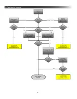
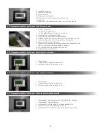
Page 26: ...26 12 4 Troubleshooting Procedure...

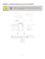
Page 27: ...maintenance on unit including filter inspection The input power to this unit is high voltage and touching any live electrical parts can cause fatal shocks or severe burns Do not touch live electrical...

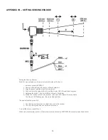
Page 28: ...bicolor LED D rapidly flashes green 5 Releases the button The bicolor LED continues to flash green 6 Within 30s insert an object into position 1 then push and release the setup button The bicolor LED...

Page 29: ...29 NOTES...
Page 30: ...are integrated with any products equipment units connections and or systems of a third party Third Party Products we hereby expressly exclude all of the following warranties express or implied namely...

Page 31: ...Order is for a customized product including without limitation any custom engineered product and b an event set forth at Section 5 2 hereof occurs you will be responsible for payment of the entire amo...

Page 32: ...An Absolent Group Company 1200 55th Avenue Montreal Quebec H8T 3J8 Email info diversitech ca For full product support visit our website https bit ly 2P6CGBX Scan above on mobile...

Reviews: